Continue to Site

Welcome to our site!

Electro Tech is an online community (with over 170,000 members) who enjoy talking about and building electronic circuits, projects and gadgets. To participate you need to register. Registration is free. Click here to register now.

  • Welcome to our site! Electro Tech is an online community (with over 170,000 members) who enjoy talking about and building electronic circuits, projects and gadgets. To participate you need to register. Registration is free. Click here to register now.

KRK 10S Subwoofer keeps blowing fuses

Status
Not open for further replies.

danwinter

New Member
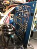
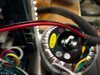
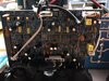
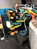
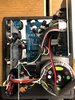
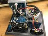
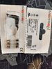
Hello all I recently got a KRK 10s that every time I plug in and turn on is blowing fuses. (got it for free knowing it does this). I am feeding it T1.6AL250V 5x20mm 1.6A 250V Slow Blow fuses so I'm pretty sure I have the correct fuse in there. I have a multimeter, know how to take readings, and have experience soldering and am taking this on as my first repair. Based on my research so far I am thinking that problem lies in the PSU. I've opened up the sub and got a good look around and I don't see anything burnt or out of the ordinary. Being that this is my first repair I figured I would consult with some people who know more than me to get a good idea of where to start trouble shooting. I attached some pics of the inside and the diagram for the circuit.
 

Attachments

  • RP10S_AMPSCH.pdf
    598.4 KB · Views: 303
  • IMG_4677.jpeg
    IMG_4677.jpeg
    1.7 MB · Views: 543
  • IMG_4676.jpeg
    IMG_4676.jpeg
    2.4 MB · Views: 411
  • IMG_4675.jpeg
    IMG_4675.jpeg
    2.8 MB · Views: 368
  • IMG_4674.jpeg
    IMG_4674.jpeg
    1.6 MB · Views: 503
  • IMG_4673.jpeg
    IMG_4673.jpeg
    1.9 MB · Views: 523
  • IMG_4672-1.jpeg
    IMG_4672-1.jpeg
    2.7 MB · Views: 887
I guess to be more specific too I am curious if I can just test the PSU to see if thats bad. Like each of these boards such as the PSU, the amp, etc. are separated and I can buy replacements. I am not super concerned about replacing individual components on the board if I could just verify that the PSU is the problem I am totally fine with just buying a new PSU PCB and calling it a day. I just want to verify that is the problem before I start throwing in new PCBs all willy nilly. Thanks!!
 
The fastest way to narrow down something is to unplug J6B, replace the fuse, plug unit to wall and turn it on. If fuse still blows then there is a problem on power supply board( may also be more) I fuse remains good then problem is further down.
 
OOOO but I just realized when I unplugged J6B although the fuse did not blow when I powered it up again. When I went to plug it back it I noticed some burn mark on the plug and realized the capacitor next to it had blown that I hadn't noticed before.
 
It would appear that the schematic is for a different but similar unit.
I believe either c411,12,13,or 14 are the ceramics shown. It is possible that the larger cap is the faulty one and has damaged the c607 cap. A shorted component(either cap) could cause the fuse to blow and second attempt with new fuse caused component to open thereby removing the short. My first suspect would be rectifier KBU602 in 42 volt supply. In circuit resistance reading should be very similar to the one on 20 volt supply.
Since you are looking to replace the defective PCB,best guess is PSU however a short further down curcuit "MAY" have overloaded the PSU to the point of failure.
 
Hi Folks,
hope you don't mind me jumping in on the thread here but I have the exact same symptoms as danwinter, but with no obvious cause (I cannot see any scorch marks or bad caps etc.).

My fuse also blows only when J6B is connected.

I'm using the fuses that were supplied by the seller (pic attached)


I bought the sub with the knowledge that the fuse "sometimes blows". Upon taking it home, I discovered that the fuse only blew when I powered it on from the switch on the rear. i.e. If I kept the switch on the unit set to "On" but powered it on from the mains switch, the fuse never blew.

Alas, now the fuse blows no matter how I power it on.

Any guidance in diagnosing the problem would be greatly appreciated!
 

Attachments

  • IMG_20210302_145049996_HDR - Copy.jpg
    IMG_20210302_145049996_HDR - Copy.jpg
    1,004.3 KB · Views: 292
wirh J6B still disconnected,, and the speaker disconnected, go to the amplifier PCB and measure with an ohmmeter between J6A pin 1 and SPK+, then measure J6A pin3 to SPK+.... my guess is one of those measurements is going to be a short circuit.... if both are open circuit or very high resistance, next thing to check is J6A pins 1 and 3 to J6A pin 2
 
wirh J6B still disconnected,, and the speaker disconnected, go to the amplifier PCB and measure with an ohmmeter between J6A pin 1 and SPK+, then measure J6A pin3 to SPK+.... my guess is one of those measurements is going to be a short circuit.... if both are open circuit or very high resistance, next thing to check is J6A pins 1 and 3 to J6A pin 2

That test will fail - as it's the wrong side of the speaker relay. Instead of SPK+ measure to the emitter resistors (R334 to 337).
 
yeah nigel thanks....i forgot about the relay.... in that case then to be blowing the fuse, one each of the + side and - side output devices must be shorted... or one of the transistors has a short through a heat sink insulator (yes there are 4 output devices).
 
apologies in delay in getting back to you...

~9.7k from J6A pin 3 to each of the large white rectangular resistors
~10.1k from J6A pin 1 to each of the large white rectangular resistors

does that seem correct?
 
does that seem correct?
yes.... now try from pin 1 tp pin 2, and from pin 3 to pin 2 of J6A. if you get a short on pin1 to pin 2 unscrew Q315 from the heatsink and tilt it away from the heatsink... if that doesn't clear the short do the same for Q317 and check again..... if the short is between pin 2 and pin 3, the other pair of transistors Q314, Q316 is where to do the same thing, remove one from the heatsink at a time.... you don't have to unsolder them... be careful not to damage the insulator between the transistor and heat sink...although if what i think has happened has happened, one of the insulators will have a hole and a black spot in it.... after seeing the ceramic cap (in the main power supply) with one side blown off, i wouldn't be surprised if a lightning strike blew a hole through one of the heatsink insulators.
 
Last edited:
Sorry for any confusion unclejed, but I'm a different person to the original poster, I don't have any visible damage on my board.
Plus, I've removed the amp board completely from the heatsink as that seemed the only way i could measure J6A to the large 5w resistors, underneath the board.

When I measure resistance between J6A Pins 1 & 2 I see it stop rising at ~93k ohms
When I measure resistance between J6A Pins 2 & 3 I see it stop rising at ~113k ohms

1616582304669.png
 
Last edited:
Status
Not open for further replies.

Latest threads

New Articles From Microcontroller Tips

Back
Top