weegee
New Member
Hi
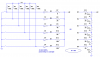
I have been told that my attempt to read a 6way DIP switch through ADC on a pic was wrong ( https://www.electro-tech-online.com/threads/digital-dashboard-circuit-review.26954/ ), so i have been googling away, and i have attached a schematic of what i have made based on my findings.
Can anyone confirm that this is an 2/r2 ladder, if it will work going from the out straight to the input on the pic.
Are there better or worse values to use for 'R' and i assume the 2R is quite literal
should these be high value, low value, or it makes no odds?
thanks again
graham