Continue to Site

Welcome to our site!

Electro Tech is an online community (with over 170,000 members) who enjoy talking about and building electronic circuits, projects and gadgets. To participate you need to register. Registration is free. Click here to register now.

  • Welcome to our site! Electro Tech is an online community (with over 170,000 members) who enjoy talking about and building electronic circuits, projects and gadgets. To participate you need to register. Registration is free. Click here to register now.

Digital Dashboard (circuit review)

Status
Not open for further replies.

weegee

New Member
Hi

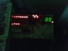
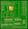
I would like some comments on my attached schematic, it is for a digital dashboard for a car. I understand digital electronics, but analogue stuff kills me.

The circuit has to run in a car, which im told is very electrically noisey, what changes if any would i need to make for this.

The dip switches in the circuit make up a 6 bit ladder type thing (R10-R15), am i right in thinking that if i read the output from this, as an analogue voltage, i SHOULD be able to decode it into what switches were set, and which ones unset.

The inputs to the circuit are 12v (well about 14.2 with the engine running), are the resistors - for example R1, R2, and R7 ok for reducing the voltage/current reaching the PIC?

Are there any other hardware related problems that you can see in the schematic, or that you would foresee with the project?

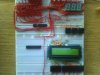
I like to try and do things myself, and usually succeed, with my breadboard ect, but this will be my first project that i will be producing on a properly manufactured PCB. (anything i should be careful with here for example component location or track placement?)

Sorry about so many questions, but if you have any for me, please ask.

i can provide any additional info you need to help me.

best regards

graham
 

Attachments

  • G-TEC DIALS.pdf
    20.4 KB · Views: 490
hi, can you explain what this means?

the highest rated 5v regulator i could find was rated at 35v.

thanks

graham
 
This is only one fairly old one. National Semi has many newer regulators for cars.
 

Attachments

  • LM2931.PNG
    LM2931.PNG
    18.8 KB · Views: 239
hi - is this suitable? its an LM2937 that i found on the RS website. I have checked the pinout and its the same, but by changing to this - is it a direct replacement??

thanks

graham
 
can anyone confirm this bit for me please:

The inputs to the circuit are 12v (well about 14.2 with the engine running), are the resistors - for example R1, R2, and R7 ok for reducing the voltage/current reaching the PIC?

it is a 22k / 10k potential divider with the output through a 1k resistor before entering the pic
 
This is just some additional info, so that you can understand exactly what i am trying to do:

Sorry just noticed i dont have any values in for C3/C4, but yes they are a ceramic and eletrolytic cap in parallell and close to the supply pins for the IC's.

The connector marked 'Input' J1 is connected to 12v ign wire, vehicle gnd, a tacho wire (on some cars a replacemnt or additional sensor may be required), a speed sensor wire, as before additional sensor may be required.

The speed and revs signal can be either 12v or 5v depending on the settings of dip switch 1 and 2 (which bypass the potential divider if 5v signals are used)

J2 'Control' is a ALPS incremental encoder with switch

J3 'LCD' is the lcd (the control is used to navigate menu's on here)

J4 'Shift' this is a row of leds, although only the first 5 are used (future proofing - connect all 8)

j5 'Speed' this is a set of 3 '7 seg' displays reasonably big ones, the ones i use just now are about 2 inch tall

j6 'Revs' this is a row of leds for display of revs (Very configurable - either one LOOOOONG line , or as i use them just now , 16 Bi-Colour leds, so that as you approch the rev limit they change color)

I also attached some pictures of what i have done on breadboard, but the aim here is to make a pcb, and i cannot afford to make a mistake.

I am no longer aiming for one big board like in my picture, but rather a small universal board about 2"x2", with everything connecting via cables. (the last pic is where i got to before starting this thread)

Thanks, and as always any other comments welcome.

PS, where is the most likely source of noise on my PCB, is there any components that need to be kept far away from each other.

The display driver (7219) refreshes at 800Hz if that makes any difference.
 

Attachments

  • dial1.jpg
    dial1.jpg
    76.3 KB · Views: 266
  • dial2.jpg
    dial2.jpg
    9.8 KB · Views: 231
  • dial3.jpg
    dial3.jpg
    92 KB · Views: 297
  • dial4.jpg
    dial4.jpg
    35.2 KB · Views: 259
  • dial5.jpg
    dial5.jpg
    24.1 KB · Views: 222
  • dial7.jpg
    dial7.jpg
    92.5 KB · Views: 303
  • dial8.jpg
    dial8.jpg
    97.5 KB · Views: 254
Last edited:
bump

I am no longer aiming for one big board like in my picture, but rather a small universal board about 2"x2", with everything connecting via cables. (the last pic is where i got to before starting this thread)

PS, where is the most likely source of noise on my PCB, is there any components that need to be kept far away from each other.

The display driver (7219) refreshes at 800Hz if that makes any difference.
 
weegee said:
can anyone confirm this bit for me please:

The inputs to the circuit are 12v (well about 14.2 with the engine running), are the resistors - for example R1, R2, and R7 ok for reducing the voltage/current reaching the PIC?

it is a 22k / 10k potential divider with the output through a 1k resistor before entering the pic
Minor nit-pick: The impedance of your divider is already (10k||22k)=6.9k. The 1k only serves to make the impedance 7.9k. You don't need the 1k resistors. I realize this is the least of your worries.
 
is this also the case when the dip switches 1 and 2 are switched, as they bypass the potential divider, so that i can use 5v inputs if the need arises, i put the 1k resistors there as an attempt to limit the current , and protect the PIC. if this is wrong could you please point me in the direction of some more info regarding this, i dont expect others to do my work for me, but i do appreciate being pointed in the right direction.

regards

graham
 
weegee said:
is this also the case when the dip switches 1 and 2 are switched, as they bypass the potential divider, so that i can use 5v inputs if the need arises, i put the 1k resistors there as an attempt to limit the current , and protect the PIC. if this is wrong could you please point me in the direction of some more info regarding this, i dont expect others to do my work for me, but i do appreciate being pointed in the right direction.

regards

graham
A thousand pardons. I missed the dip switches. :eek:
 
no problem, lol

so will the resistors (1k) ones actually do anything to prevent damage to the pic? or are they just wasting board space. I remember people putting in resistors on each of the data lines when interfacing with the pc, so i thought id put them in and hope for the best.

cheers

graham
 
I have decided to remove the extra 6 dip switches, that i was trying to read, as at my current level with analogue electronics it is beyond me. I have also replaced the 2 dip switches for bypassing the potential divider with simple jumpers (as i have these, and i dont have 2 way dip switches).

So the board is now designed, and i have attached a 3d mockup of it. Can anyone foresee any problem with the component positions? from an electrical noise point of view??

All being well, i'll have my first batch of professionally made pcb's back in about 10 days :)

thanks for all the help and assistance i have been given, and i'll update you when i have my board back if they work.

In the meantime im gonna study more analogue electronics.

regards

graham
 

Attachments

  • expected.gif
    expected.gif
    46.5 KB · Views: 205
Russlk said:
The 5 volt regulator should be rated to withstand 60 volts input (load dump).
True, spikes as high as 60V can occur but don't bother with a regulator rated for 60V, use an LM7805 which is rated for 35V and stick a 28V zenner across the input.
 
This looks good, is this project finished? I am looking for a similar circuit. Weegee can I base a project on these plans or do I need to pay someone? Thanks
 
Status
Not open for further replies.

Latest threads

New Articles From Microcontroller Tips

Back
Top