Continue to Site

Welcome to our site!

Electro Tech is an online community (with over 170,000 members) who enjoy talking about and building electronic circuits, projects and gadgets. To participate you need to register. Registration is free. Click here to register now.

  • Welcome to our site! Electro Tech is an online community (with over 170,000 members) who enjoy talking about and building electronic circuits, projects and gadgets. To participate you need to register. Registration is free. Click here to register now.

Is it possible to determine voltage from this schematic?

Status
Not open for further replies.

swervyn

Member
Hello people :)

Wondering if it is possible to determine the voltage from this circuit diagram at the WV1 terminal?

This is the inlet valve of a dishwasher that is showing a fault code. Seems that it is either related to the inlet valve or possibly a control board short.

The inlet valve is one of the aqua stop valves with a solenoid built into the hose, like this one:

https://goo.gl/images/JGc8Mh

Power supply is 240V. I have removed the valve connector from the board and taken a reading across the terminals on the control board with the dishwasher powered up, reading shows around 70V AC

Basically trying to determine whether to buy a new aqua stop hose or if the control board is cooked, throw the dishwasher in the bin.

Preference would be to repair to save $$$ but not wanting to spend $100 on a hose that may not be the problem. Googling has not really given me any answers how to test the valve, but assume to connect voltage, turn on the water and see if the valve opens & closes as it should. The 70V reading on the control board is throwing me a bit.

Dishwasher is about 15yo so has had a good run with a few repairs by me over the years, latest being a replacement pump.

Just trying to be a tight wad and repair if possible and get another couple of years out of it :)

Plus I hate washing dishes by hand!

6adp_5656_whm1.jpg
 
As far as I'm aware the inlet valves are 240V (and the schematic, such as it is, shows that), you may not be getting a correct reading because you're using a digital meter, and it's switched via a triac. Easy to see if the board is switching or not, simply connect an incandescent bulb (such as a table lamp) to WV1 and see if that lights up when the water is supposed to turn on.
 
If you are reading 70v, most likely you are reading current leakage thru a snubber circuit.

Nigel's idea is a good one. Drive a small incandescent light bulb and see what it looks like. and measure the voltage across it.
 
If you are reading 70v, most likely you are reading current leakage thru a snubber circuit.

Nigel's idea is a good one. Drive a small incandescent light bulb and see what it looks like. and measure the voltage across it.

Emphasize small, certainly not more than 25 watts. I doubt the control circuitry is designed to supply more than 100 mA or so, and if you overload it you may damage what was a good board.
 
Emphasize small, certainly not more than 25 watts. I doubt the control circuitry is designed to supply more than 100 mA or so, and if you overload it you may damage what was a good board.

The crude schematic shows a triac feeding the valve (which is what you're likely to use), and triacs don't often come particularly tiny, so it's probably at least a 1A triac, so there should be no problem. However, a pygmy lamp would be a good idea anyway.
 
Thanks guys, will try a small lamp later today and report back. If it is indeed 240V, should I then be ok to apply direct voltage to the valve to check open/close operation?
 
Ok, latest update is 240V test lamp did indeed light up when machine cycled on, so seems control board is ok. (And showed 240V with multimeter). Pulled hose & valve out and connected to water supply & 240V and the damn thing worked. I did whack the valve a couple of times with a wrench first which may/may not have fixed a sticky valve. Powered up and off numerous times and the valve worked fine. At this point I realised I could not be stuffed trying to resurrect a 15yo dishwasher so went out and bought a new one lol. And typically researched online the one I was going to buy and ended up with a completely different and more expensive one :banghead: Had the valve shown a fault or the control board shown a fault I would have been more satisfied, the machine has had a minor leaking problem for a while and I just figured it is not worth the hassle of trying to diagnose the fault code so opted for the easy way out.
Thanks to all for suggestions & ideas
 
A 25 watt lamp is really 100 watt load. The poster does not know what he is talking about. A very dangerous suggestion.
But, then again, he IS an electronics expert.
 
Last edited:
The comment should have been 100 watt load. The spell-check change the word.

The resistance of a lamp is only one sixth of its final resistance and thus a 25watt lamp will "ask-for" the equivalent of 100 watt load when it is starting to illuminate and this is enough to either damage the driver transistor or completely fail to get any response at all.
NEVER use a lamp as a piece of test equipment in an electronic circuit unless you have enormous driving capability.
 
A 25 watt lamp is really 100 watt load. The poster does not know what he is talking about. A very dangerous suggestion.
But, then again, he IS an electronics expert.

I think we all know who doesn't have a clue round here :D - an incandescent lamp is an excellent dummy load for a huge number of purposes, and this application is one it's excellent for.

As you don't have a clue what you're on about, and obviously didn't even bother reading the thread, why bother posting at all?.
 
My mind hurts LOL never hurt nothing using a lamp as dummy load in my life even works to see if a CB is outputting power

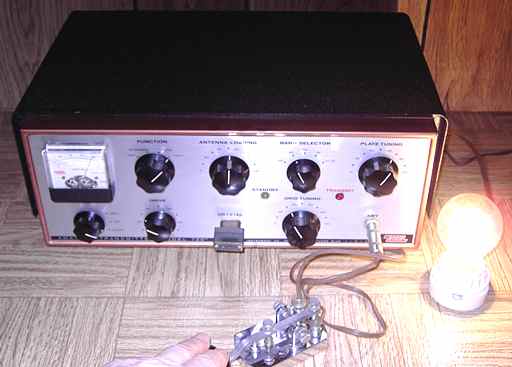
Here one on a transmitter
Eico720.jpg

Here is a nice setup
**broken link removed**
 
Someone pointed out:
I doubt the control circuitry is designed to supply more than 100 mA or so, and if you overload it you may damage what was a good board.
So, if you think a lamp will take 100mA when illuminated, it will require 500mA to start to turn ON. So, this is the point I am making.
 
Someone pointed out:
I doubt the control circuitry is designed to supply more than 100 mA or so, and if you overload it you may damage what was a good board.
So, if you think a lamp will take 100mA when illuminated, it will require 500mA to start to turn ON. So, this is the point I am making.

So why do imagine a triac feeding a solenoid valve is only capable of feeding 100mA?, and even assuming it was, that's the continuous current - try looking up the surge ratings of triacs.
 
Most dishwasher solenoid valves are only less then 10 watt's so use a 10 watt bulb but a 25 is not going to hurt it
that's only a 104.167 mA load.
I'm sure the triac or relay, They use lot's of relay's to on dishwasher boards too so I'm sure it handle a Amp or 3

Like Nigel Goodwin said it's a good test I use it all the time too but yes you got use your head and
not put a 500 watt bulb use a small one I have used 7 watt 25 , 50 , 100 something close to what i'm checking.
 
Status
Not open for further replies.

Latest threads

New Articles From Microcontroller Tips

Back
Top