Continue to Site

Welcome to our site!

Electro Tech is an online community (with over 170,000 members) who enjoy talking about and building electronic circuits, projects and gadgets. To participate you need to register. Registration is free. Click here to register now.

  • Welcome to our site! Electro Tech is an online community (with over 170,000 members) who enjoy talking about and building electronic circuits, projects and gadgets. To participate you need to register. Registration is free. Click here to register now.

Ir_xmitter circuit challenge

Status
Not open for further replies.

ulot

New Member
Hello, i'm trying to create an IR xmitter but my transistors keep burning up i'm not sure why.

I've attached the circuit. due to the exact signal i'm trying to recreate, i'm to get 38khz pulses to represent a zero and just a HIGH output to represent a ONE.

I'M using an 18f4550 PIC,

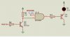
RC7(UART TX PIN) is connected to a transistor to invert the signal, and then to a terminal of an AND gate

a PWM signal at 38khz, 50% duty cycle is connected is connected to a second terminal of an AND gate

the output is fed to a transistor, which powers a IR-LED
However, the PNP just keeps heating up and damaging my IR leds.
what could be wrong?

I simulated with PROTEUS and it works fine.
The exact transistor AND and resistor values are included

Please i'll really appreciate some help
thanks.
 

Attachments

  • IR_XMITTER_SCH.jpg
    IR_XMITTER_SCH.jpg
    75.4 KB · Views: 171
It's burning up because there's no resistor to limit the current through the LED. LEDs are diodes and the current is limited primarily by the external circuit, which is this case is whatever the transistor can supply with the given base current and transistor gain. Didn't you notice on the data sheet that there's a maximum current rating for the LED?

Unfortunately simulators don't usually show that the LED and/or transistor will blow under those circumstances. If you measure the LED simulation current, it likely is well above it's maximum rating.

You need to add a resistor in series with the LED. It's value would be R = (Vs-Vd)/Id where Vs is the supply voltage, Vd is the LED voltage drop (from the data sheet), and Id is the desired LED current.
 
Thanks alot i'll do that
Unfortunately, we don't have a standard electronics market here, we usually get components from local repair stores who have no technical knowledge.
That was a big oversight on my path. Thanks
 
If you check my PIC tutorials there's a circuit (and code) for doing IR remote control, your's is far too complicated - no need for any extra bits apart from the transistor, LED, a capacitor and resistors. Generating the 38KHz is dead simple in software, and more accurate than using pwm, with each 'burst' been an exact number of 38KHz cycles. The LED series resistor is absolutely essential, although it will be far lower than you might think, because you pulse the LED at an amp or so.
 
Thanks again for your help.
I actually went that way because i need a specific output pattern, which i've attached along with Nigel's IR circuit.
Can i get that output pattern from your circuit Nigel?
 

Attachments

  • IR_PL3201.jpg
    IR_PL3201.jpg
    14.4 KB · Views: 159
  • board5.gif
    board5.gif
    3.6 KB · Views: 129
Last edited:
Status
Not open for further replies.

Latest threads

New Articles From Microcontroller Tips

Back
Top