Continue to Site

Welcome to our site!

Electro Tech is an online community (with over 170,000 members) who enjoy talking about and building electronic circuits, projects and gadgets. To participate you need to register. Registration is free. Click here to register now.

  • Welcome to our site! Electro Tech is an online community (with over 170,000 members) who enjoy talking about and building electronic circuits, projects and gadgets. To participate you need to register. Registration is free. Click here to register now.

IR to PIC

Status
Not open for further replies.

RMIM

Member
Hi

I'm trying to get Nigel’s Sony IR tutorial to work. (I don’t have an LCD display) – I keep hitting 1,2 and 3 on my universal remote (set for Sony) but nothing happens (The LED does not come on).

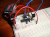
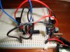
Originally I had my IR receiver-out going through a transistor – it was already set up like that for another circuit and was working. I noticed that Nigel’s circuit did not use a transistor. I have now removed the transistor and added a resistor in the right place. Still does not work.

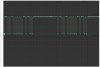
Looking at the output on the oscilloscope the trace sits on 5v till you hit a button. Then you get a train of pulses between 5v and 0v. Should it not be the other way round?


My traces (1st picture) don’t look like any of the classic textbook (2nd pic) examples of what you are supposed to see. Or maybe I don’t know how to use my oscilloscope?

Where am I going wrong?

Regards
 

Attachments

  • SONY IR.jpeg
    SONY IR.jpeg
    125.9 KB · Views: 217
  • text book example.gif
    text book example.gif
    2.9 KB · Views: 167
Last edited:
looks like your switch is bouncing

the transistor (havn't looked at Nigels schematic?) but I bet it is connected as a debounce or your code needs a debounce sequence.
just my first impressions.
 
Birdman: I copy pasted it. (Almost)

The original started off with
-----------------------------------------

LIST p=16F628 ;tell assembler what chip we are using
include "P16F628.inc" ;include the defaults for the chip

-----------------------------------------

The pic I'm using is a P16F628A so I stuck an A in there.

LIST p=16F628A
include "P16F628A.inc"

Normally I have one of the following lines

; __CONFIG _CP_OFF & _WDT_OFF & _PWRTE_ON & _BODEN_OFF &_INTRC_OSC_NOCLKOUT & _MCLRE_OFF & _LVP_OFF
__CONFIG _CP_OFF & _WDT_OFF & _PWRTE_ON & _BODEN_OFF &_INTRC_OSC_NOCLKOUT & _MCLRE_ON & _LVP_OFF

I choose one then I have to have MCLRE pin 1 or 0 to get the pic to work.
I tried to include that line - but it did not build correctly. So I left it out.

Im not sure whether MCLRE should be on or off with Nigel's code.


(The other circuit had a transistor to invert the IR signal - I was using a HT12A IC with HT12D.)


Nigel: Thanks for the info. Why I cant I see something that looks like start pulse in my trace?


MRDeb: Nigel's circuit has no transistor for the IR Receiver.
 
Because that's not a Sony SIRC's waveform - and won't work.

OH! - Well I have tried several other sony codes for tv. Can't universal remotes be used for this project? Or am I just not programming the remote correctly?

I take it, it would be possible to slightly modify your code to be used with any signal? Using an oscillocope you can get all the info you need?
 
Last edited:
OH! - Well I have tried several other sony codes for tv. Can't universal remotes be used for this project? Or am I just not programming the remote correctly?

A universal remote should work identically to a Sony one, you're most probably not programming it correctly.
 
A universal remote should work identically to a Sony one, you're most probably not programming it correctly.
Amazing stuff Nigel – had a universal remote on an old HTC phone. Tried that and it worked 100%. Traces on the oscilloscope are exactly what they should be.

Not sure what is up with the other remote control – perhaps a terrible misprint for all the SONY codes? The remote is easy enough to program: hold done set then press tv – now tap in 3digit code.

Would have been there for a long time if you did not point out it was not actually sending SONY waveforms. Thanks Nigel and thanks for the tutorials.
 
I too tried the same tutorial with a universal remote. Absolute disaster, I couldn't figure out what was going on. I gave up in the end.
Maybe I'll try again ( since I've built the hardware ).
 
I too tried the same tutorial with a universal remote. Absolute disaster, I couldn't figure out what was going on. I gave up in the end.
Maybe I'll try again ( since I've built the hardware ).

There were about 16 different codes for Sony TV. I tried them all - none of them gave anything like a sony waveform. I tried the Sony CD code. That gave something more like a sonywave form - changed the device ID in Nigel's program from tv 0x00 to CD 0x11 and it worked 100%. Would not have had a clue what was going on without an oscilloscope and Nigel pointing out it was not a Sony waveform. Try using another Universal remote.

Another spanner in the works was my circuit did not work from my 9v battery and 7805.

Originally I was powering the circuit from my laptops USB. Circuit worked 100%. Button 1 would toggle the LED. Buttons 2 and 3, On and Off respectively.

Once everything was working I decided to switch over to battery power. Everything stopped working. Granted my circuit is lacking in capacitors, actually I don’t have a single one - need to buy some.

But very weird behaviour: The circuit refused to work at all. There was a wire hanging out of the bread board, it was plugged into the negative, by chance I held on to the end and noticed the circuit started to work 100% as it should.

Can someone please explain this phenomenon to me - it's dangerous, someone could seriously lose their sanity over this - I can even push button 2 to turn the LED on and nothing happens. I then touch the wire and magically the LED comes on. I can then push button 3 and nothing happens, touch the end of the wire and again magically it turns off the light. What's going on? (Wayyyy, I have made a touch lamp) How do we avoid this kind of thing in circuits we build? What is it called? I was very lucky I noticed this early on. Circuit works normally when powered from USB 5v.

Dont give up house of wax - IR and RF are great things to master. Home automation/Robots all things fun are wireless it's magical.
 
Last edited:
Still can't shake the problem - the circuit will only work if I touch it with a finger.

I have now added all the capacitors as per Nigels diagrams. Still no luck.

But most of my pins are floating, could this be causing the trouble? Don’t have any 10k resistor to try and tie them down.

I have read you should turn unused pins to Output pins.

What else can I do? Is this a common problem?

My tutorials are all 100% guaranteed working - and there's no need to take any special precautions with unused I/O pins.

How have you built it?, have you followed my veroboard layouts?.

The most common cause of 'finger touching' is letting MCLR float, my tutorials all switch it to be an I/O pin, so it's connected internally.

Set config to 0x2118 for the 628A.
 
Set config to 0x2118 for the 628A.

Thanks Nigel. But what does the above even mean? :eek:

Change the
__config 0x3D18 ;sets the configuration settings (oscillator type etc.)

to 0x2118

or add that line in?

Built on a bread board (why is that bad?)

I'm sort of new to pics - but have not read the tutorials in sequence, so maybe there a few basics I have missed out on.
 
Last edited:
1) What is the white wire doing, its going from ground to ground?

2) Take out the ICSP and take another picture, thats extra wires for nothing!

Which wire do you need to touch to make it work??
 
1) What is the white wire doing, its going from ground to ground?

2) Take out the ICSP and take another picture, thats extra wires for nothing!

Which wire do you need to touch to make it work??

Yesterday I got hold of that bread-board. Rubbish. The power rail is not continuous. It’s broken, so I used the white wire to bridge the gap.

I was using another better quality bread board, but it was doing the same thing, so I moved it to this one. I might move it back.


Yesterday you had to plug a spare wire in + or – or even the IR output and hold on to it. The circuit would then work.

Today you could even just hover a finger near the unused pins on the pic RA2 RA3 RA4 (by the way, these pins are unused by me. They are however active in the program. I think they are used for a LCD – but I don’t have one yet – I did try to erase all lines of code that had anything to do with the LCD but could not get it working. So I just went back to the original code to rule out a mistake from that.)

Right now it seems only a wire plugged in RA3 and holding the other end will make the circuit work.
 
attempt 3000.

Now it does not work unless the scope is attached and i touch i wire connected to a pin

oops forgot the 47uF capacitor between IR ground and R2 in this pic. still does not work properly though.
 

Attachments

  • b.JPG
    b.JPG
    133.7 KB · Views: 145
  • a.JPG
    a.JPG
    125 KB · Views: 146
Last edited:
Status
Not open for further replies.

Latest threads

New Articles From Microcontroller Tips

Back
Top