Continue to Site

Welcome to our site!

Electro Tech is an online community (with over 170,000 members) who enjoy talking about and building electronic circuits, projects and gadgets. To participate you need to register. Registration is free. Click here to register now.

  • Welcome to our site! Electro Tech is an online community (with over 170,000 members) who enjoy talking about and building electronic circuits, projects and gadgets. To participate you need to register. Registration is free. Click here to register now.

Inverting Schmitt Trigger Help!

Status
Not open for further replies.

random77

New Member
Hi all,

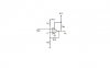
I'm trying to design an inverting schmitt trigger for my circuit (see attached file). I managed to design a non-inverting schmitt trigger but becuase of the feedback loop connecting the input I have a feeling it's screwing up the input signal in the rest of the circuit. I know I can use a buffer to isolate the signal but it's generating other problems.. I know that with the inverting configuration the input is isolated from the feedback so I suspect signal won't be affected.

I'm using a LM393 comparator and according to the data sheet a pull-up resistor is needed (they suggest a value of 3k). When I do node voltage analysis I get the equation in the document attached. But when I get my values for my resistors from these equations, my circuit does not work at all! Am I doing something retarded? Please help!

Thanks!

FYI: The threshold voltages for my design are:
Vlower = 0.1V
Vupper = 0.3V
 

Attachments

  • Inverting Schmitt Trigger.JPG
    Inverting Schmitt Trigger.JPG
    13.1 KB · Views: 310
  • Schmitt Calculations.doc
    69.5 KB · Views: 205
Last edited:
hi Random,
What are the resistor values on the inverting circuit .?
Also what is the signal input detail.?
 
hi Random,
What are the resistor values on the inverting circuit .?
Also what is the signal input detail.?

Hi eric,

I've uploaded some more info in the doc file.

But, essentially the signal represents a pulse for every heartbeat. The pulse lasts for about 10-20ms and the amplitude of this pulse varies depending on how far the transmitter is away from the receiver, but if there's no pulse, the input into the schmitt trigger is ~0V and anything above that I'd like to count as a pulse. Note that the received signal has been amplified and filtered and the noise in the signal is about 10mV. So I decided to set the lower threshold to be 0.1V.

There's also bit of ripple (approximatley 0.2V) in the amplitude of the signal so I've set the hysterisis to be 0.2V as well. Therefore, the upper threshold is set to 0.3V.

The two equations that I derived in the doc file are pretty hard to solve simulatenously - but the values I got were:

R1 = 24.5K ohms
R2 = 4400 ohms
RFB = 100K ohms

Hope that helps!

Thanks!
 
hi,
Look at this pdf.
I will check your calcs and post back

EDIT:
If you would post a circuit diagram with the revised component values, I will check it out for you in simulation.
 

Attachments

  • hysteresis1.pdf
    76 KB · Views: 418
Last edited:
Hi Eric,

Thanks for the pdf! That was really helpful - much easier to solve than my version of that schmitt trigger. I've got the ratio of resistors for R1 and R2 and the value for Vref now which I'll try and implement tomorrow. Hopefully my calculations are correct!

Cheers

EDIT: If you can simulate the values for me, that will be great - I'll post them up soon.
 
Last edited:
Hi Eric,

Here is the revised schematic

Cheers

EDIT: Vref is actually meant to be 0.104V - so just approximate it to 0.1V I suppose
 

Attachments

  • Schmitt Revised.JPG
    Schmitt Revised.JPG
    13 KB · Views: 232
Last edited:
hi Random,
The Vref is too high, the 0 to +0.5v signal never passes the threshold.

Look at the LTspice simulation plot.

EDIT:
this 2nd image is closer, I would use resistors for 0.1V from the +5v line.
 

Attachments

  • random2.gif
    random2.gif
    24 KB · Views: 226
  • random3.gif
    random3.gif
    27.2 KB · Views: 224
Last edited:
hi,
This should do what you are asking.
 

Attachments

  • random4.gif
    random4.gif
    33.5 KB · Views: 219
Hi eric,

Thanks for all of that. I'm just wondering in your last schematic - is there any purpose for R4? Also is C1 used to ensure that any noise in the supply voltage gets shorted through it?

Cheers
 
Hi eric,

Thanks for all of that. I'm just wondering in your last schematic - is there any purpose for R4? Also is C1 used to ensure that any noise in the supply voltage gets shorted through it?


Cheers

hi,
I always add a series resistor to OPA/Comp inputs, its gives protection against heavy currents flowing into the inputs.
C1 as you say is a simple noise filter.
If you require an adjustable voltage threshold, change the 200R to a 500R variable, be aware the threshold change will change the hysteresis a little.
 
Hi Eric,

Thanks for all your help - I tested it out with the rest of my circuit and it works as expected which is great!

Cheers
 
Status
Not open for further replies.

Latest threads

New Articles From Microcontroller Tips

Back
Top