Continue to Site

Welcome to our site!

Electro Tech is an online community (with over 170,000 members) who enjoy talking about and building electronic circuits, projects and gadgets. To participate you need to register. Registration is free. Click here to register now.

  • Welcome to our site! Electro Tech is an online community (with over 170,000 members) who enjoy talking about and building electronic circuits, projects and gadgets. To participate you need to register. Registration is free. Click here to register now.

input and save input

Status
Not open for further replies.
This is not that hard
Screenshot from 2017-12-29 02-39-48.png
 

Burt, the one thing missing from your schematic is the 100kΩ pull down resistor. Without this pulldown resistor (could be a pullup if you'd rather) connected to the ADC input; this pulldown resistor ensures a known state with no button pressed. Without it, the value will be all over the place when no switch is pressed. I will bet that MrDEB either has this resistor in the wrong place, or it's the wrong value.

Of course any number of coding issues could be in play too, but hardware seems the most likely.
 
I was just showing the spread of voltage where is he getting the reading he got don't no.
This is with all 2 k
you take adc reading at P1
Screenshot from 2017-12-29 03-25-05.png

**broken link removed**
 
I entirely understand that Burt and I know you understand why a pullup or pulldown is needed to have a defined idle state. But MrDEB needs the details spelled out since the question has been asked before AND he peobably has said resistor in the wrong place.
 
Burt, your switches are shorting out a whole bunch of resistors. Move them so the taps get connected to the input with a large pulldown on the input. Post 126 works. However, so will post 1637 (page 90), probably.

Mike.
 
That just give 10 values it works too i can't see how he got 184, 256, 276,309,320,363,384,407,431,461
i was just playing with qucs
this is how i do it
sw1.png

i cant see how he got them crazy values.
 
I get a 400 plus mV between switches hes showing 50 mV and less
don't make sense to me.
And I don't let it go to 0 volts ground anything under 400 mV is error.
and using a Pic 16f1825 I couldn't press the buttons fast enough to not get the right readings
And I tried a arduino to they both worked out about the same.
 
I have the breadboard wired just as in post #126. I tried your suggestion and only part of the ladder outputs correctly. Tried Mikes suggestion and it was slightly better. Maybe after I have the circuit on a PCboard the circuit will work as suggestions?
My best results were 1024/10 and 1024 / 20 but the circuit failed when I got to resistor junction 5 or 6.
I have 12 resistors in series with the junctions soldered together. Using a jumper wire and alligator clips so LOTS of possible issues.
After I order boards and assemble, I will redo the CASE SELECT as needed.
Another issue may be the resistor values. Supposed to be 1% 1K.
 
If you put 11 resistors of equal value between V+ and ground, you have to end up with 10 values uniformly spaced between V+ and ground.

If you don't get that, either the circuit is wrong or the measurement is wrong. Those are the only options.
 
Your results are totally bogus but rather than figure out the problem, you're going to build a circuit board? Your bread board can't have so much resistance to change the results significantly.

And how could resistors of 5%, 10%, even 20% tolerance cause the results to all clump to the middle of the expected span? This is trivial voltage divider atuff. It must work - you have something SCREWED UP.

FIND THE PEOBLEM AND FIX IT.
 
Also, if you want to use the simulation to find out what the ADC reading would be, just replace the 5V supply with 1023.
Could be easier than converting back and forth.
 
Screenshot from 2017-12-29 09-31-03.png

it wants it to be kV but its about dead on the real thing i just used a bunch 1k and a wire for the switch darn it works on the breadboard too
 
I have 12 resistors in series (2-1K to equal the 2K resistor. That leaves 10 resistor junctions between V+ and Ground
I measure 4.66v between V+ and ground (I have the Pickit2 powering the circuit)
the A0 input to ground = 99.8K
From ground end of ladder to V+ end = 11600K (remmber there are 12 resistors.
voltages starting from the first junction (after the 2K resistor) 1.72v
at the V+ end the junction measures 4.32 volts
Will draw out a diagram.
wondering about the FUNCTION math?
FUNCTION Get_ADC_Sample() AS WORD // Function to grab the ADC sample for player position

result = (ADC.Read(0)+1)*500/1024 // Grab an ADC sample from channel 0
END FUNCTION
 
Will check my circuit etc. after I get lunch and clear my head.
 

Attachments

  • new ladder.JPG
    new ladder.JPG
    71.3 KB · Views: 160
There seems to be an ECHO ECHo ECho Echo echo in HERE HERe HEre Here here.

As explained by me, Tumbleweed and possibly others, there is no need and indeed no logical reason to convert the ADC readings to volts. Not only is your conversion wrong (since its reference is Vdd of some 3 volts, not 5), but it's counter productive. Why do a bunch of math to get a fractional number that you'll have to use more math to get to s usable form for your Select comparison. Remember, INTEGER numbers!

I suggest you search the Swordfish help file for ADC and look at the examples on how to use it. But no conversion is needed. The raw values will range from 0 - 1023. This is exactly what you need.

Or, you could add a voltage reference, read the supply voltage for each measurement and from that calculate the true voltage reading for each switch measurement and use floating point numbers for each comparison. This will not change the outcome in the slightest, make your code much larger and more complicated, add $$ cost to each and every unit built and ensure this forum thread reaches 50 pages.

Look up voltage dividers - it doesn't take a rocket scientist to see you should have essentially uniform readings between each switch.

Look up ratiometric output - this follows from voltage dividers and you should be able to understand why you don't want or need to use a voltage reference in this kind of application.
 
I have 12 resistors in series (2-1K to equal the 2K resistor)
I think most of the examples everyone is showing are using all 1K resistors, so get rid of the "2K" resistor and just use a single 1K in its place.

Then, try this code:
Code:
Select ADC.Read(0)
     Case <25
           'no button pressed
     Case <100       ' ideal=92
           'button 1 pressed
     Case <200       ' ideal=185
           'button 2 pressed
     Case <300       'ideal=278
           'button 3 pressed
     Case <400       'ideal=371
           'button 4 pressed
     Case <500       'ideal=464
           'button 5 pressed
     Case <600       'ideal=557
           'button 6 pressed
     Case <700       'ideal=650
           'button 7 pressed
     Case <800       'ideal=743
           'button 8 pressed
     Case <900       'ideal=836
           'button 9 pressed
     Case <1000       'ideal=929
           'button 10 pressed
     else
           'something is wrong
End Select
It uses the reading directly from the ADC chan 0 instead of converting it to volts.
If you look at the cases there's some wiggle room added to each one... that should take care of any adc inaccuracy/resistor tolerance.
The first limit for button 1 (case < 100) may be a little tight, so you could always increase that a bit to say 125, but there's probably enough slop in the others to work ok.
 
Why are people using 11/12 resistors. All that is required is 10 resistors and the calculation is switch = (ADCin+51)/102 - must be integer maths.

Mike.
 
That's why I don't do it with 10 you never get a 0 and map function I use works really good with the
lowest reading not being use.
But you can use 10.

Just to add a little 'story' to this method of using switched resistors and an A2D for reading multiple switches.

This technique was used a LONG, LONG time ago on early JVC VCR's - back before IR remote controls they used to use a corded remote, which used a 3.5mm jack plug, and a number of switched resistors inside the remote.

Nice idea, but poorly implemented - for two reasons:

1) One of the buttons switched directly across the cable, giving 'zero' ohms (I think it was the Play button - in any case, it was one commonly used).

2) The next button up from that (the next lowest resistor value) was the record button.

So this gave an unfortunate result, the cable for the remote tended to get bent and twisted, and started to give significant resistance in the cable. So when you pressed 'Play' it could inadvertently go to Record instead, erasing what you were trying to watch - which could be quite disastrous. I repaired countless remotes for this fault, replacing the existing wire with thin microphone cable, and a new 3.5mm jack plug.

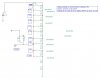
I see that you aren't using 'zero ohms', but it still might be a good idea to consider which button you use for each option, just in case something strange happens (like a poor contact in a switch, giving a higher resistance reading).
 
Status
Not open for further replies.

Latest threads

New Articles From Microcontroller Tips

Back
Top