Continue to Site

Welcome to our site!

Electro Tech is an online community (with over 170,000 members) who enjoy talking about and building electronic circuits, projects and gadgets. To participate you need to register. Registration is free. Click here to register now.

  • Welcome to our site! Electro Tech is an online community (with over 170,000 members) who enjoy talking about and building electronic circuits, projects and gadgets. To participate you need to register. Registration is free. Click here to register now.

Information about Electric Tester Circuit.

Status
Not open for further replies.

huzeeigat

New Member
Hello Everyone,

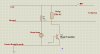
Please provide me with info on the basic Electric tester circuit which we use in our homes to test live and neutral connections,and which also comes in-built in a screw-driver with a small neon l.e.d. If anyone has any links of how the circuit works please post it here..Need it urgently.

Thanks,
Huzefa :)
 
Alec_t I have the basic information on this..but i need to develop this circuit on my own..for application purpose..

Thanks,
Huzefa
 
A basic tester is no more than a neon bulb with a series resistor. I have no idea what the mains voltage is at your location or how for example residential power is wired? So a basic tester is a neon lamp and a series resistor and a more detailed tester would be three lamps and three series resistors. Here is one example of an AC Outlet tester. Beyond that, more information would be needed as to exactly what you want.

but i need to develop this circuit on my own..for application purpose..

Then post a few of your ideas and drawings. Then work from there but at least make a few basic drawings based on what you think will work for you.

Ron
 
Guessing that India uses 240 V ground referenced. So you need three indicators. One that measures across the line and one that measures from the line to ground without drawing much current. Neon bulbs fit that description. They require a series resistor.
The low current would prevent setting off GFCI's. The Third indicator would measure ground to ground and would generally be off. If it's lit, there would be reverse polarity.

So, you would get depending on what lights were lit:
Wired right
Reversed polarity
No ground
No power

Some testers can create a 10 mA path to ground at the push of button to test the operation of a GFCI.

Personally, I follow up the test with an Ideal SureTest which measures a lot more.

I mounted a string level on the typical outlet tester to make it simple to mechanically level the outlets.
 
A basic tester is no more than a neon bulb with a series resistor. I have no idea what the mains voltage is at your location or how for example residential power is wired? So a basic tester is a neon lamp and a series resistor and a more detailed tester would be three lamps and three series resistors. Here is one example of an AC Outlet tester. Beyond that, more information would be needed as to exactly what you want.


Then post a few of your ideas and drawings. Then work from there but at least make a few basic drawings based on what you think will work for you.

Ron

Hi Reloadron,

I have made a simple circuit for the electric tester..just chek if it is a proper one..
 

Attachments

  • ELECTRIC_TESTER.png
    ELECTRIC_TESTER.png
    31.6 KB · Views: 331
Also Reloadron, i wanted to ask the amount of light this neon lamp would generate in order to drive a phototransistor or a photodiode....
 
Also Reloadron, i wanted to ask the amount of light this neon lamp would generate in order to drive a phototransistor or a photodiode....

I have made a few homebrew opto couplers using NE2 lamps. While a neon lamp does not output much light they output enough for a photo transistor to work. However, there are off the shelf store bought solutions that would likely work better. The circuit testers mentioned are merely for checking a circuit, now if you want to do something with the results there are other ways to go about it. Really a matter of exactly what you want to do.

Ron

Hi Ron,

I wanted to make a shock protection circuit..I am uploading the circuit for the same..

I have a device..which is operated through a relay..the electrical ground is nothing but the metal body of the device..as is in every device.. Now the relay in the diagram controls the switch..if Live and neutral are in same postion..the device would be on..and if interchanged..the relay would not turn on...Now if the live and neutral are in place..and if the relay is not charged..there is a possibility that a direct current flow through the body of the device..thereby making it hazardous... i just wanted to make shock prevention circuit..as connected in diagram...where the photodiode and neon lamp would be kept in a close housing.. Please suggest me how can i implement this circuit..or if any more suggestions you have..

Thanks,
Huzefa
 

Attachments

  • Shock_prevention.png
    Shock_prevention.png
    5.5 KB · Views: 285
OK, there are a few problems with your circuit. The photo transistor is not going to like the AC current. So lets take a look at a very basic AC line test circuit.

**broken link removed**

That simple little circuit is based on standard AC Outlet in US Code Wiring. The idea will be the same so let's look at what is going on. Remember that Ground is connected to Neutral where power enters so Ground and Neutral should be the same point electrically.

When power is normal DS1 and DS3 will be illuminated and DS2 will be off.

If Line and Neutral are reversed DS2 and DS1 will be illuminated and DS3 will be off.

If Ground is missing (open) DS1 will be illuminated and DS2 and DS3 will be off.

Think about the logic here and what makes each lamp be on or off.

So we could replace DS1 and DS3 with two small AC line voltage relays and let them sort of serve as an AND gate. Two conditions must be true for both relays to be energized. The normally open contacts of those two relays could be placed in series for a load.

There are many ways to do this and this is just an example to get you going and thinking about what conditions must be met in a safe circuit. Relays are simple devices to get the idea from.

Ron
 
Hey Ron,
If we replace DS1 and DS3 will the circuit serve to be shock proof? as the device body is being used as Ground in my case. I'll work with the circuit you have provided and Post the image again.

Also wanted to ask in your circuit,the power enters from which side from up or below?
Thanks,
Huzefa
 
Last edited:
The ideal shock proof is actually a GFCI (Ground Fault Circuit Interrupt) placed in the mains line. A GFCI looks at the circuit current. Think about a simple load on a circuit. Matters not if the load is 1 Amp, 5 Amps or whatever. The idea being current out is equal to current in. So if we have a Line and Neutral and measure the current in each leg that current should be the same. Kirchoff's laws of voltage and current make that pretty clear. So the best way to eliminate a potential shock hazard is through the use of a GFCI. Give this a read.

Even with a good correctly wired circuit things can go wrong. When things do go wrong and someone is shocked we want to remove the power in an instant. That is what a GFCI does. So we can have a small circuit to tell us if the AC power is wired correctly as to Line, Neutral and Ground and also a circuit that will kill power instantly if a person is receiving a shock. There is a big difference between the two.

Beyond the human shock hazard there are other reasons to monitor power. This is true in both single and poly phase AC circuits. AC Motors for example can be sensitive to over or under voltage conditions. We may want circuits to shut down systems when the wrong conditions exist.

schmitt trigger, there are AC Input photo transistor devices including AC Input SCRs that are quite common.

Ron
 
Status
Not open for further replies.

New Articles From Microcontroller Tips

Back
Top