Continue to Site

Welcome to our site!

Electro Tech is an online community (with over 170,000 members) who enjoy talking about and building electronic circuits, projects and gadgets. To participate you need to register. Registration is free. Click here to register now.

  • Welcome to our site! Electro Tech is an online community (with over 170,000 members) who enjoy talking about and building electronic circuits, projects and gadgets. To participate you need to register. Registration is free. Click here to register now.

Inductive Kick and Snubber help

Status
Not open for further replies.

Njguy

Member
I really need help on this one, it's confusing and it's holding up my project.

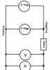
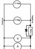
I have two inductive loads on a parallel circuit. Electromagnets. I was wondering how to set up rectifier diodes to prevent the inductive kick that destroys hardware. I don't know anything about them. I don't know which ones to buy, or where to set them up on a parallel circuit. Actually i don't even know how to attach them to a wire and in what direction. I have never used them.

My inductive loads operate at around .7 amps on a 12 volt parallel circuit.
 
Last edited:
Typically inductive loads have signal diodes connected 'backwards' in parallel across them to prevent this type of damage.
 
Also, pretty much any diode will work for this. I recommend the very common 1n4002. A 1n4148 would likely work as well. Both are cheap and easy to find.
 
Last edited:
**broken link removed**

See Image A.

I see the diode on that diagram, but what is that other symbol? Has a third wire branching off. Also I had originally thought that the diode would be against the negative wire not the positive. So does the diode basically reroute the kickback current so it avoids hardware like the relay? It only lets current pass in one direction?
 
Last edited:
Also, pretty much any diode will work for this. I recommend the very common 1n4002. A 1n4148 would likely work as well. Both are cheap and easy to find.

at around .7 amps

I believe a 1N4148 would be blown by that amount of current it's trying to clamp.

The problem with using a 1N4001 type is that they are slow and don't clamp quickly, so the leading edge of the inductive spike goes by unclamped and damages things. A Schottky diode is much better because it's a lot faster. What you want is the class of diode known as "ultra fast recovery" for clamping inductive transients.

A series R-C snubber is faster yet.
 
Last edited:
Ignore the transistor; only the relay and the diode is relevant to your purpose. The location of the diode in relation to the positive or negative supplies depends entirely on your application, what is important is that the anode of the protection diode is on the negative side, and the cathode on the positive side: hence 'backwards' or 'antiparallel' to the inductor.
 
I drew up a little diagram, my relay is on the main line, not in one of the parallel branches. Both of these mags are turned on at the same time. Would someone be able to just throw the relay into the drawing. Doesn't have to look good, just so i can get it.
 

Attachments

  • Circuit.jpg
    Circuit.jpg
    18.9 KB · Views: 364
Hope you were serious about it not having to look good :D

That's a pretty confusing diagram by the way, the power supply arrangement isn't very clearly marked but I assume the positive and negative labels refer to the connection points they're closest to on the diagram.
 

Attachments

  • Circuit.jpg
    Circuit.jpg
    20 KB · Views: 268
Last edited:
By the way, the electromagnets will require protection diodes in a similar configuration, as they are also inductive loads. Probably bigger ones in fact. Of course unless there's something sensitive to the brief voltage spike in the circuit, you shouldn't need any of the protection diodes anyway though.
 
Last edited:
........
The problem with using a 1N4001 type is that they are slow and don't clamp quickly, so the leading edge of the inductive spike goes by unclamped and damages things. A Schottky diode is much better because it's a lot faster. What you want is the class of diode known as "ultra fast recovery" for clamping inductive transients........
A common overdesign that's not supported by my experience.

The diode only has to be faster than the slower of the transistor, or the inductor. In the case of the 500ns 1N400x, the inductors that we're protecting don't normally have magnetics capable of sub microsecond spike edges.
 
The problem with using a 1N4001 type is that they are slow and don't clamp quickly, so the leading edge of the inductive spike goes by unclamped and damages things. A Schottky diode is much better because it's a lot faster. What you want is the class of diode known as "ultra fast recovery" for clamping inductive transients.

A series R-C snubber is faster yet.
Fast diodes are rated for turn-off time, not turn-on. Most diodes are quite fast in the turn-on (clamp) direction, so any diode will generally work. Fast diodes may be described as "ultra fast recovery" but recovery time (time to turn-off) is not the issue for a clamp diode, it's the turn-on time.
 
A common overdesign that's not supported by my experience.

The diode only has to be faster than the slower of the transistor, or the inductor. In the case of the 500ns 1N400x, the inductors that we're protecting don't normally have magnetics capable of sub microsecond spike edges.
If you say so.

The rise time of the "spike edge" is determined by one thing only: the di/dt of the current change in the inductor, and it doesn't matter what kind of inductor it is.
 
Last edited:
The rise time of the "spike edge" is determined by one thing only: the di/dt of the current change in the inductor, and it doesn't matter what kind of inductor it is.
Inductance and di/dt isn't the only factor to consider. The rise time is also modified by stray/parasitic capacitances and that is affected by the type/size of the inductor.
 
Fast diodes are rated for turn-off time, not turn-on. Most diodes are quite fast in the turn-on (clamp) direction, so any diode will generally work. Fast diodes may be described as "ultra fast recovery" but recovery time (time to turn-off) is not the issue for a clamp diode, it's the turn-on time.

Inductance and di/dt isn't the only factor to consider. The rise time is also modified by stray/parasitic capacitances and that is affected by the type/size of the inductor.

crutschow hits it out of the park twice.
 
Inductance and di/dt isn't the only factor to consider. The rise time is also modified by stray/parasitic capacitances and that is affected by the type/size of the inductor.
Whatever. Considering how cheap fast diodes are, I just don't see the wisdom of using junk diodes for clamps. You know that transistor the diode is protecting? Well, if the diode is a shade slow for the peak of the kick, then the transistor gets beat on with narrow duration voltage spikes that gradually punch it through. If you are betting the life of the transistor on it ALWAYS being so much slower than the diode you know the di-dt rate, you better specify the transistor. Me, I use fast diodes for snubbers and junk diodes for rectifiers. makes life simple and means the transistors live their natural life span. I am thrifty, but snubbers ain't where I try to save three cents. I have reworked too many power converters that smoked because my boss pinched pennies on the snubber.

And BTW, turn on times for junk diodes are never a guaranteed (or tested) parameter and I never pin the survival of the main part on an untested parameter. I have seen semiconductors from Taiwan and China that were garb age all wearing the industry standard JEDEC number because they meet the TESTED limits... and the rest of the specs, who knows?
 
Last edited:
Status
Not open for further replies.

Latest threads

New Articles From Microcontroller Tips

Back
Top