I believe a 1N4148 would be blown by that amount of current it's trying to clamp.
The problem with using a 1N4001 type is that they are slow and don't clamp quickly, so the leading edge of the inductive spike goes by unclamped and damages things. A Schottky diode is much better because it's a lot faster. What you want is the class of diode known as "ultra fast recovery" for clamping inductive transients.
A series R-C snubber is faster yet.
Are these the Schottky diodes you were referring to? If so which one exactly cause I'm not very competent when it comes to diodes.
All Electronics | Electronic and Electro-Mechanical Parts and Supplies at Discount Prices
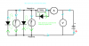
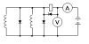
") The voltmeter is correctly connected now.
The voltmeter is correctly connected now.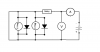
")