Continue to Site

Welcome to our site!

Electro Tech is an online community (with over 170,000 members) who enjoy talking about and building electronic circuits, projects and gadgets. To participate you need to register. Registration is free. Click here to register now.

  • Welcome to our site! Electro Tech is an online community (with over 170,000 members) who enjoy talking about and building electronic circuits, projects and gadgets. To participate you need to register. Registration is free. Click here to register now.

Induction Heater Driver Problems

Status
Not open for further replies.

Lighty

New Member
Hi All

I've wanting to build a induction heater, but not winning much with it.

The problem is as soon as I power it up, it either blows the fuse (10 Amp) or pops the Mosfets.

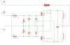
I have attached the schem of the circuit used.

I have tried various mosfets (IRF540, IRFZ44N, IRFP460) all the same.

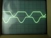
However if I only power up the +15V (LM7815) side and place my scopes probes onto the gates, I can see its oscillating, at roughly 120khz if I recall correctly, however the waveform doesn't appear to be correct, and it would appear that the gates are both high for a fraction of a second, and the voltage levels seem to be funny, with low only going down to 2.2V and high only going to 3.8V.

+24V is from a rectified Toroidal transformer with a 15000uF cap. rated for 10amp.

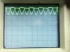
The work coil is 8 turns of 4mm copper tubing, the coil is 60mm diameter and 55mm long. It is centre tapped to form 4+4 turns.

I've tried various arrays of capacitors for C1 (22nF to 4uF), but it still won't start up and keeps popping fuses etc.

Any assistance would be greatly appreciate!

Thanks in advance

Justin
 

Attachments

  • IMG_3450.JPG
    IMG_3450.JPG
    2.1 MB · Views: 1,009
  • IMG_3452.JPG
    IMG_3452.JPG
    1.8 MB · Views: 1,046
  • driver.png
    driver.png
    6.9 KB · Views: 6,024
For reliability you may want to expand on your circuit by going to dedicated gate driver IC's and an independent oscillator driver.

IR2110 or IR2113 or similar dual gate driver IC's are a good place to start. With a bit of clever feedback circuit design you should be able to design a self regulating feedback loop that changes its frequency as the inductance changes similar to your self oscillating one you have now.

Just a thought.
 
Thanks for your reply tcmtech!

I picked up some IR2110, IR2113 and IR2111 ICs from my local store.

I'm a but confused as to how to implament it. on the spec sheet diagrams it show the output from the mosfet as only being 2 wires, where I'm using a work coil with 3 wires (centre tapped).

I also got a SG3524, which I thought I could use to generate the PWM waveform?

Sorry, I'm rather lost with this at the moment......:confused:

Thanks
 
Just reconfigure the high side driver part of the output pair on the IC's to be the same as the low side driver.

That way one IC can work as a push pull driver circuit instead of a half H bridge driver circuit. From there you could use your SG3524 to control the gate driver IC's two inputs.
 
I'm not sure on how to acheive this but will do some homework. :eek:

I've been reading through the spec sheets, and the SG3524 it a fixed frequency device, so not sure how I would make it resonate with the tank circuit as the load chances.....

Does anyone know of a good circuits out there? can't seem to find anything other that Royer ocsillator circuit, which clearly don't work for me...:mad:
 
To change the high side driver over to work as a second low side driver in the same IC you just need to connect the two high side pins as Vb to Vcc (Pin 7 to Pin 3) and Vs to Com (Pin 6 to Pin 2).

I don't recall how exactly a SG3524 is externally synchronized to a feedback loop to make it work as sort of a phase locked loop but it has something to do with the oscillator circuit and it needing a 2x frequency over what ever the resonant frequency of the driven coil assy is.

To get the 2x frequency a pickup coil is full wave bridge rectified and the resulting AC from that coil gets turned into DC with a high ripple voltage which is what the oscillator circuit uses or something like that.

I think but I could be wrong though.

The other option would be to use the feedback coil to drive a pair of op amp comparators that in turn drive the IR2113 gate driver IC's inputs 180 degrees out of phase plus with that you could have an adjustable zero crossing dead band that can be used to set the duty cycle.
 
I think u need a bit of a deadband in your pulses as the capacitance of the FETs induce a delay in switching which could cause them to create a type of shoot thru in your circuit.
You should be able to simulate a deadband by placing a 12V zener in series rev biased config in front of the fet gates. That way only the full 12V should hit the gates and the rise/fall times are cut off and don't overlap.
 
Your circuit looks like the Mazzilla driver circuit. Ideally you should use mosfets of at least 3 to 4 times the supply voltage rating to allow for a safety margin.
In your case I would suggest IRFP250 or IRFP260 mosfets which are rated for 200 Volts and 30 or 46 Amps respectively.
 
Thanks tcmtech, I'll look into that.

Mosiac, I'll give that a bash and check if it helps? Thx

Hi Rodalco, as far as I know its called a Royers Ocsillator, perhaps the same thing? but could be mistaken?
I'm currently testing with the IRFP460 rated at 500V, didn't help.


The funny thing it that I know it does work, couple people have built them, just can't understand why mine is not, have checked the circuit 100 time to confirm its correct.
 
You sometimes have to tweak initial conditions to get oscillation in Spice, e.g. set a cap voltage to a non-zero value.

Edit: I've just run an un-tweaked LTSpice simulation with no problem. C1 was set at 100nF and each L was set at 10uH. BTW, did you include a K directive to couple L1 and L2?
 
Last edited:
Lighty, A Royer Oscillator usually has a feedback winding as well. and the working coil has one winding instead of a centre tapped winding.
 
Hi Rodalco

Thanks for that feedback, i'm with you and understand. Live and Learn I say.

Still no luck with this....:mad:

@ tcmtech, I setup the SG3524 with the IR2113 driving a single mosfet, I dropped the centre tapped work coil for a std 4 turn (also tested 8 turn) coil, but still no luck, the Mosfets fry long before the work piece gets hot, though sometimes I could feel it starting to get worm. Tried various resonent frequencies and adjust the SG3524 to suite, but wasn't long, 5 seconds before the fuse (10A) popped or if the fuse didn't the mosfet on a 2"x2" heatsink was cooking after 10-15 seconds.

So frustrating......
 
What frequency does it run at?
Are you sure L is 3 Mh and large enough not to saturate?
Maybe you could put a little R in series with it to measure the current. - quickly :rolleyes:
 
I've adjusted capacitors to adjust Hz from about 40khz to about 160khz...

L3 was bought from an electronics company rated at 3.5mH and 6 amps, though my meter measures it at about 3mH. Size wise its about just over 30mm OD.
 
Seems like it should work.
By the coil diminsions 0.39 Ufd should be good.
Are the diodes fast high voltage types?
 
Last edited:
They are BYV26E and have a recovery time of 75nS and 1000V.

Going to try find a bigger L3 inductor, and test it.

Tried making an array of the L3 inductors, using 4 in series/parallel config which helped. didn't pop the fuse on start up and mosfets didn't seem to get as hot.

Perhaps the circuits is just current hungry? is there a calculator somewhere to calculate the current draw at resonence Hz with no load? I can understand the high consumpusion while heating.
 
Going by your rough specs you are using a DC power source with roughly a 34 VDC open circuit voltage smoothed out by a 15,000 uF capacitor as a power source for a HF push pull type induction heater circuit correct?

First thing I question is the ESR of the 15,000 uf capacitor. Do you have any other smaller low ESR capacitors in parallel with it being you are tying to pull up to a 120 Khz pulse train off of it at peak currents of 10 amps or more?

Second given a push pull circuit design your theoretical peak voltages each switching device may have to deal with would be 68 volts add in any inductance spikes and limited clamping and they could be seeing 10X that!

Third if you are seeing a 10 amp average current drain the switching devices themselves may be seeing 3 - 5 times that peak currents as well.

If it was me I would be tempted to try and redesign the circuit initially into a H bridge with low ESR capacitors making up one half of it and your switching devices making the other.

Once you have the bugs out of that then I would change the capacitor side of the H bridge over to switching devices and run the induction coil in series with the two capacitors paralleled with each other that made up the second side of the H bridge.

That's basically how most of the large induction heater units are configured.

That's my thoughts anyway.:D

(But I did just roll out of bed too. :eek::p)
 
Eureka we have gold....or induction heating!

Ok, so I've has some success, although not working without problem, it is working!

The Mosfet aren't burning up and I can get a thin blade knife red hot, though if I put anything "heavier" it pops the fuse (Fuse 2).

I have attached a schematic of the now "working" circuit, now to just tweek it to and pump it up a notch.:)

Just some other info:

- When the fuse pops, its always FUSE 2.

- The transformer driving the circuit is a 4x 25V 5Amp toroidal transformer (secondaries are isolated)

- The LM7812 does seem to get extreamly warm.
 

Attachments

  • driver.png
    driver.png
    13 KB · Views: 2,139
Going by your rough specs you are using a DC power source with roughly a 34 VDC open circuit voltage smoothed out by a 15,000 uF capacitor as a power source for a HF push pull type induction heater circuit correct?

Correct

First thing I question is the ESR of the 15,000 uf capacitor. Do you have any other smaller low ESR capacitors in parallel with it being you are tying to pull up to a 120 Khz pulse train off of it at peak currents of 10 amps or more?

I have a 15,000uF + a 2000uF in parallel, both 63V, but not sure on their ESR.


Second given a push pull circuit design your theoretical peak voltages each switching device may have to deal with would be 68 volts add in any inductance spikes and limited clamping and they could be seeing 10X that!

This I why I tried the IRFP460 rated at 500V, not sure if it was correct thing to do though?


Third if you are seeing a 10 amp average current drain the switching devices themselves may be seeing 3 - 5 times that peak currents as well.

If it was me I would be tempted to try and redesign the circuit initially into a H bridge with low ESR capacitors making up one half of it and your switching devices making the other.

Once you have the bugs out of that then I would change the capacitor side of the H bridge over to switching devices and run the induction coil in series with the two capacitors paralleled with each other that made up the second side of the H bridge.

That's basically how most of the large induction heater units are configured.

That's my thoughts anyway.:D

(But I did just roll out of bed too. :eek::p)

Will look at other design, but would like to get this up and running 100%, even though it may not be the best, reallity is that battling sometimes forces you to learn something new, and I got plenty to learn.:eek:

Thanks tcmtech!:)
 
Status
Not open for further replies.

Latest threads

Back
Top