Continue to Site

Welcome to our site!

Electro Tech is an online community (with over 170,000 members) who enjoy talking about and building electronic circuits, projects and gadgets. To participate you need to register. Registration is free. Click here to register now.

  • Welcome to our site! Electro Tech is an online community (with over 170,000 members) who enjoy talking about and building electronic circuits, projects and gadgets. To participate you need to register. Registration is free. Click here to register now.

InchWorm & 16F628A -not supported?

Status
Not open for further replies.

lemonyx

New Member
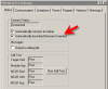
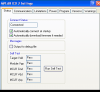
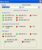
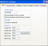
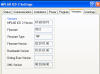
Thanks to William, my Inchworm now works. I am trying to program a 16F628A, but the error msg says "MPLAB ICD 2 does not support programming this device if both the internal oscillator and internal MCLR are selected." Operation Aborted (Warning 32).

Where and how do I make this adjustment to turn off one or the other in MPLAB? If that is what I am to do.


HELP- newbie


TIA
 
Last edited:
Change the config setting in your code. Change _MCLRE_OFF to _MCLRE_ON or _INTOSC_OSC_??CLKOUT to another setting.

If you have a hex value for your config then work it out yourself. Maybe someone here that thinks hex values for configs are a good idea can advise.

Mike.
 
The ICD2 is not generally a VPP before VDD programmer, the Inchworm+ had a small PFET added to address this but it's a workaround. You have to toggle MPLABs target power control manually every time.

Just follow Pommies advice and add the _MCLRE_ON if you're using the internal OSC. You will lose MCLR as an input pin and have to use a small pullup resistor on it when in use. 22K is good.
 
Thanks Pommie & William for getting back. This code is already written for a VFD clock, so if I start changing something in the code, the thing might not work. But I'll try it and see what happens.

Just in case - William what is that "toggle MPLABs target power control manually every time." How would I do this in MPLAB?


The Code
The PIC16F628A has just enough i/o for my purposes: 4 for the BCD-Decimal converter to drive the grids, 8 for the anodes, one each for the hours and minutes buttons, one for the 60Hz input, and one for the PWM output driving the boost converter. In other words, where there is a will, there is a way. To wit: B<7:4>,A<3:0> segments
B<3> dc/dc PWM out
A<6>,B<2:0> grid (BCD)
A<7,5> switches: hours, minutes
A<4> 60 Hertz input


Clock Multiplicity
The 60Hz counting part of this is the same as it's always been, except that I'm not interrupting on the 60Hz input; instead, I interrupt at a subharmonic (4kHz) of the PWM frequency (64kHz), trapping rising edges of the 60Hz clock while performing the grid muxing.

Why do it this way? Trying to be synchronous with two different clock sources whose frequency and phase relationship is not well known (and can change, e.g., with temperature, since we're using the onboard RC oscillator in the PIC) is a nasty problem. In digital design you call this clock domain spanning problems or the like, whereas in soft/firmware it generally shows its ugly face in the form of asynchronous interrupt contention. Instead, it's much better to synchronize the slower clock to the faster, which works well as long as you can take delays in the slow clock on the order of one cycle of the faster clock. Since we're just counting the 60Hz cycles, and not really synchronizing anything to them, we can certainly get away with it here.

To trap the 60Hz cycles, I'm still using timer 0 in external clock mode, but keeping the timer 0 interrupt disabled. Every 4kHz muxing cycle I poll the timer 0 flag (INTCON,T0IF), which is set even if the interrupt is disabled, and manually clear it and reset the prescaler when it flips over. This lets me take advantage of the hardware at my disposal to get rid of an appreciable chunk of code.


Here's a snipet of the code:

RADIX hex
processor p16f628a
LIST p=p16f628a
LIST n=0
LIST r=hex
LIST st=on
LIST f=inhx8m
include p16f628a.inc
__CONFIG _BODEN_ON & _CP_OFF & _DATA_CP_OFF & _PWRTE_ON & _WDT_OFF & _LVP_OFF & _MCLRE_OFF & _INTRC_OSC_NOCLKOUT
__CONFIG _BODEN_ON & _CP_OFF & _DATA_CP_OFF & _PWRTE_ON & _WDT_OFF & _LVP_OFF & _MCLRE_ON & _INTRC_OSC_NOCLKOUT


; DAC control bits
#define mswitch PORTA,0x05
#define hswitch PORTA,0x07
#define gridmsb PORTA,0x06
#define gridm2sb PORTB,0x02
#define _segper PORTB,0x07
#define gridpar grid,0x00
#define grswap grtmp,0x00
#define _is_pm ampm,0x00
#define _is_50 clkconfig,0x07

; A<0:3>,B<4:7> - segments
; A<4> - 60Hz inputs
; A<5> - grid MSB
; A<6:7> - min:hr inputs
 
Last edited:
Thanks William for the link.

Another problem has cropped up. The 7805 is getting very, very hot. Burned myself touching the heat sink. I was using a 13vdc 1000ma wall wart, with this it gets hot quick, with a 12vdc 750ma, it just takes longer to get very, very hot. Hot enough that the power light went out.

Even with a 12vdc 500ma wall wart the heat sink gets hot to the touch. It's only hooked up for 3 minutes or so. I have re-soldered all the connections. Tried to find the post that described this sme problem but the search came up blank - for me.

TIA
 
With nothing hooked up to the inchworm the 7805 will run warm to the touch, a 200ma draw will get it slightly hot. Putting a current meter on the power supply or the target will help trace why the heat.

The Inchworm draws between 30ma & 60ma. Not enough to get too warm. Is the MAX232 warm / hot? it should be cool to the touch, a hot may indicate a probem with one of the tansistors (but MPLABs power diagnostics should report a problem)
 
I found the problem- I inserted the 16f628a backwards in the zif socket - duh

William - How would I do this?

You have to toggle MPLABs target power control manually every time Very new to MPLAB or even programming

TIA
 
lemonyx said:
I found the problem- I inserted the 16f628a backwards in the zif socket - duh

William - How would I do this?

You have to toggle MPLABs target power control manually every time Very new to MPLAB or even programming

TIA
Programmer / Settings / Power

Uncheck "Power target circuit from ICD2" make sure the EXT5V jumper is open and your target (firefly) will shut off. You can then erase/reprogram a PIC with MCLR & INTOSC active.

The new Firefly Assembly manual has PIC + ZIF programming socket pictures.
 
Last edited:
whew !!! thanks to all of you i am finaly burning my 16f628 succesfully.

but... the led doesnt blink any more. It just stays on.
I am trying Nigels following program. I changed the config bits from 3d18 to 3d38 to switch MCLR.

any ideas ... ?

Code:
;Tutorial 1.2 - Nigel Goodwin 2002
 LIST p=16F628  ;tell assembler what chip we are using
 include "P16F628.inc"  ;include the defaults for the chip
 __config 0x3D38   ;sets the configuration settings (oscillator type etc.)
 cblock  0x20    ;start of general purpose registers
  count1    ;used in delay routine
  counta    ;used in delay routine 
  countb    ;used in delay routine
 endc
 
 org 0x0000   ;org sets the origin, 0x0000 for the 16F628,
     ;this is where the program starts running 
 movlw 0x07
 movwf CMCON   ;turn comparators off (make it like a 16F84)
    bsf  STATUS,  RP0 ;select bank 1
    movlw  b'00000000'  ;set PortB all outputs
    movwf  TRISB
 movwf TRISA   ;set PortA all outputs
 bcf STATUS,  RP0 ;select bank 0
Loop 
 movlw 0xff
 movwf PORTA   ;set all bits on
 movwf PORTB
 nop    ;the nop's make up the time taken by the goto
 nop    ;giving a square wave output
 call Delay   ;this waits for a while!
 movlw 0x00
 movwf PORTA
 movwf PORTB   ;set all bits off
 call Delay
 goto Loop   ;go back and do it again
Delay movlw d'250'   ;delay 250 ms (4 MHz clock)
 movwf count1
d1 movlw 0xC7
 movwf counta
 movlw 0x01
 movwf countb
Delay_0
 decfsz counta, f
 goto $+2
 decfsz countb, f
 goto Delay_0
 decfsz count1 ,f
 goto d1
 retlw 0x00
 end

P.S: have moved this post from another thread to this more appropriate one
 
Alright got it working :D
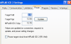
. I was not being blind enough in following the instructions. Thought I wouldnt require the +5 v to MCLR pullup if I dont want to use RA5 for i/o. dumbo me :)
 
My guess is you don't have the internal oscillator running.

Change
__CONIFG 0x3D38
To
__CONFIG 0x3F18 ; this will use the internal OSC

Now remember the bit you insist on setting MLCR, it's an input only never an output so putting LEDs on it will do nothing.

If you pull up MCLR with a 22K resistor to +5 change your config line to.
__CONFIG 0x3F38
 
hi Bill. did we post simultaneously or is that really an reply to my post.

I have things up and running using conf = 0x3D38. I just had to add the pull up resistor of 15k from +5 to MCLR/RA5.
 
William

I'm getting a new error msg now. #32

The MPLAB is using a newer OS than that which was installed with this system's version of MPLAB IDE. This newer OS may not work correctly. We reconmend

And that was the end of the error msg. I looked in programmer - settings - error, but that was it of the msg. Looking on the Micrchip web site is daunting for me - I don't know what I'm doing, but I'm learning as I go.

I've re-installed the OS using your instructions, hoping that would fix the problem, but no go.

I thought that it would be easy to "burn a chip", now I know better. Any help with this?

I tried your wrk around with changing the settings but I'm guessing with this error nothing will work.

Charles
 
You should never have to download the OS after it's installed the first time. There is a setting somewhere to enable automatic OS download. I'm running the same firmware as you and MPLAB 7.60 (make sure you're running the latest MPLAB)

Here are some screen shots from MPLAB. Make sure your version is the same as one of the screenshots.
 

Attachments

  • MPLAB Firmware.png
    MPLAB Firmware.png
    7.2 KB · Views: 152
  • Download Automatic.png
    Download Automatic.png
    11.1 KB · Views: 150
  • ICD2 settings.png
    ICD2 settings.png
    8.2 KB · Views: 134
William


How do I change this now?
 

Attachments

  • mplab icd2.png
    mplab icd2.png
    25.7 KB · Views: 137
  • mplab icd.png
    mplab icd.png
    29.6 KB · Views: 137
Last edited:
The bootloader versions are identical, the reason for the Legacy and 16F and the Firmware revision is normal as I had an different PIC selected on the config menu so a different OS will show. I'll try it with a 16F628 (not A I'm assuming)


Edit, figured it out.

You need to from MPLAB choose the PIC you want to program / debug first (It will then automatically download the proper OS)

You have a 16F877 chosen, you need to select a 16F628

So from MPLAB

Configure / Select Device
And change it to the 16F628
 

Attachments

  • SelectDevice.gif
    SelectDevice.gif
    14.1 KB · Views: 137
Last edited:
William

Here's some of the screen shots after each option. In configure/select device it's the 16F628A that I select.

The version does not change.

Again the code that I am using was not written by me and I can't change any of it or the device will not work correctly - as I did before (but it did program?)
 

Attachments

  • select.png
    select.png
    11.3 KB · Views: 140
  • pwr.png
    pwr.png
    17.5 KB · Views: 131
  • proj.png
    proj.png
    9.7 KB · Views: 123
  • proj2.png
    proj2.png
    65.8 KB · Views: 121
  • status.png
    status.png
    24.9 KB · Views: 158
  • comm.png
    comm.png
    11.4 KB · Views: 144
  • version.png
    version.png
    21 KB · Views: 143
  • error.png
    error.png
    26.6 KB · Views: 141
Hmm what PIC is on the inchworm? A 16F877-20 or 16F877A.

This is the screen I need to see.

Connecting to MPLAB ICD 2
...Connected
ICDWarn0030: MPLAB ICD2 is about to download a new operating system. If MPLAB IDE is just starting, it will appear to "hang" at the splash screen. Please be patient. MPLAB IDE will finish it's intialization after the OS is downloaded. (Note: You may wish to select to ignore this warning in the future.)
Downloading Operating System
Connecting to MPLAB ICD 2
...Connected
Setting Vdd source to target
Target Device PIC16F88 found, revision = b1
...Reading ICD Product ID
Running ICD Self Test
...Passed
...Download Operating System Succeeded
Setting Vdd source to target
Target Device PIC16F88 found, revision = b1
...Reading ICD Product ID
Running ICD Self Test
...Passed
MPLAB ICD 2 Ready
 
Last edited:
Status
Not open for further replies.

Latest threads

New Articles From Microcontroller Tips

Back
Top