Continue to Site

Welcome to our site!

Electro Tech is an online community (with over 170,000 members) who enjoy talking about and building electronic circuits, projects and gadgets. To participate you need to register. Registration is free. Click here to register now.

  • Welcome to our site! Electro Tech is an online community (with over 170,000 members) who enjoy talking about and building electronic circuits, projects and gadgets. To participate you need to register. Registration is free. Click here to register now.

Important features to have on 18F4620 Board?

Status
Not open for further replies.

Krumlink

New Member
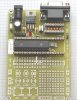
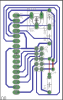
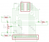
Well right now as far as electronics goes, I have been working on a little 18F4620 control board, and I have figured out what ports will do what:

PORTA Motor Control, LED output for Motor controls
PORTB Sensor Interaction/LED indicators
PORTC Sensor Interface?
PORTD Dunno?
PORTE Use E0,E1 E2 (E3 is reset, want to have that seprate) as LED indicators

Problem is, that I have a lot of pins and ports to work with (take that Basic s*** 2)

So I was wondering what should I do with Port C and Port D? I was thinking of using them and bringing the pins to a LCD board (I understand the basics of LCD's now :)) and I am thinking that would be a good idea.

I have each port brought out to 2x5 headers (awesome idea by 3v0 on his boards) and I could easily change the function if needed. I have a HD74480 LCD so I can easily communicate with it, and I have already programmed a LCD with my uPICFAT to display "WHAT CHU TALKIN BOUT WILLIS" on it. I have also just started with INPUT commands too, and by taking data from an input and displaying it on the LCD (button input).

So what should I do with entire PORTC and PORTD?

www.crosstheroadelectronics.com for the uPICFAT (I got mine for free, the guy who sells them is a mentor on team 217 Thunderchickens who is visiting my HS today :D)
 
The 2x5 port connector goes back a long way. They may have existed on the targets I used back in the mid 70's.

I think you are on the right track already. I would not try to use up the ports. Keep them available via the 2x5's so you can add functionality as you need it.

EDIT: On could argue that you do not need such a large chip. Given that you do not know what your final robot will look like I like the idea of the extra ports.
 
Last edited:
I was going to have Ports ABCD on 2x5 headers, and have E0,E1 E2 and E3 (E3 is reset) as dedicated LED's and E3 as a reset. I will then have seperate boards that go from the port I need (say, a PORT D LCD board).
 
I would definitely fit an LCD as it makes debugging so much easier. Breakpoints and single stepping are great until you get time critical stuff. For the rest of the ports, I agree with 3v0, keep them free until you need them.

What language are you using?

Mike.
 
That is the normal character based LCD data sheet. What makes you think it isn't?

Mike.
 
I got confused a bit. I think I have a different LCD than that :confused:
 
There are LCD that have different connectors. Does yours have the 7*2 connector on the left hand side?

Like this,
**broken link removed**

Mike.
 
Last edited:
OK. I have everything all figured out, and I really confused myself. I have the HD44780 LCD and how to interface with it. LOL.
 
Mine has the 16x1 header. It is a 16x2 LCD, and the uPICFAT does not utilize all 8 data lines, but I will have to use 2 ports to use the LCD (read write) if I wanted to use all 8.

EDIT: I have decided to utilitize all 8 data lines, taking up an entire port. I also have the option to change what module to use on it too. I then need a Read/write control, and a instruction/register select line. :)
 
Last edited:
I would definitely fit an LCD as it makes debugging so much easier. Breakpoints and single stepping are great until you get time critical stuff. For the rest of the ports, I agree with 3v0, keep them free until you need them.

What language are you using?

Mike.
But that pretty much requires dedicating pins on the PCB layout that might be needed for some other project.

I'm beginning to think that using a dedicated PIC as an LCD interface which supports SPI, I2C, or Serial connection to a host device might not be a bad idea. Then all you need is 1, 2, or 3 wires from any project board to connect to the LCD (and keypad perhaps?) when you need it.

Mike

<added>

The first general purpose PIC proto' board I designed (2003) had a 28 pin footprint within a 40 pin footprint which allowed me to use either type of chip on the same board. I wish I had had the foresight to install 10 pin dual row connectors for each port (great idea)...

proto-28-40-board-jpg.19671
 

Attachments

  • Proto 28-40 board.jpg
    Proto 28-40 board.jpg
    51.1 KB · Views: 604
Last edited:
I am making this on a radioshack perf board, because I wanted to be able to make this somewhat quickly. In the future I can make a PCB if this design works well.

I have come up with a sweet acronym as usual :)

ViPER
Versatile Programmable Experimental Robot

awesome eh?
 
I made a few LCD adaptor boards. It allows you to connect a 1x14/16 LCD to a standard 2x5 port in the 4 bit mode. No need to dedicate pins to the LCD if it is only used during debug.
lcd2x5-png.19672

lcd2x5sch-png.19673


It is single sided. The red line above R1 is a jumper.
I can post pdf's of the foil or the eagle files if anyone wants them. Not a difficult board to layout.

EDIT: R2_OPT and R3_OPT can be used in place of the 5K pot.
 

Attachments

  • lcd2x5.png
    lcd2x5.png
    10.2 KB · Views: 625
  • lcd2x5sch.png
    lcd2x5sch.png
    6.2 KB · Views: 809
Last edited:
3v0,

Hook the LCD backlight Anode to VCC and put the backlight Cathode on the unused connector pin where I can drive it with a sinking PWM signal and that adapter would be perfect...

I have a similar manufactured adapter but they hard-wired the backlight to power pins (with appropriate dropping resistor) and the R/W pin to ground. It's got two unused pins on the 2x5 connector but I can't cut the backlight and R/W connections because they're buried. Bummer!

Mike

**broken link removed**
 
Last edited:
Changed as requested. Also made the board a bit easier to etch and solder. The pdf fils is a foil pattern that can be printed and etched. The zip file contains the Eagle sch and brd files.

1b_sch-png.19676

1b_brd-png.19677
 

Attachments

  • 1b_sch.png
    1b_sch.png
    8.7 KB · Views: 621
  • 1b_brd.png
    1b_brd.png
    11.8 KB · Views: 515
  • LCD_4Bit_16_TO_10_ADAPT_1B.pdf
    12.5 KB · Views: 205
  • LCD_4Bit_16_TO_10_ADAPT_1B.zip
    23 KB · Views: 157
3v0,

Very nice. "Perfect" does indeed apply. I'll take two (grin).

I meant to edit my post to say it would be nice to have the backlight cathode available on the connector so that I could drive it with PWM or ground it but I couldn't edit my post.

btw, I wouldn't be opposed to a installing a couple jumpers if those small traces between pads is a problem...

Mike
 
Last edited:
3v0,

Very nice. "Perfect" does indeed apply. I'll take two (grin).

I meant to edit my post to say it would be nice to have the backlight cathode available on the connector so that I could drive it with PWM or ground it but I couldn't edit my post.

btw, I wouldn't be opposed to a installing a couple jumpers if those small traces between pads is a problem...

Mike

Are you saying you want the anode hard wired to +5 and the cathod to the connector pin. As in I have is bas awakards? If you think I still do not understand mark up the schematic using a paint program.

The lines between traces should not be a problem with a decent setup. The thin lines here are .012 and I have used .001. The .012 is quite dependable but the .001 traces need to be verfied after etching. Most of the time they are good.
1b1_sch-png.19683
 

Attachments

  • 1b1_sch.png
    1b1_sch.png
    8.6 KB · Views: 688
Last edited:
Yes, backlight anode to VCC and cathode to the connector. Sorry I didn't notice it in your first updated drawing.

Mike
 
Status
Not open for further replies.

Latest threads

New Articles From Microcontroller Tips

Back
Top