Continue to Site

Welcome to our site!

Electro Tech is an online community (with over 170,000 members) who enjoy talking about and building electronic circuits, projects and gadgets. To participate you need to register. Registration is free. Click here to register now.

  • Welcome to our site! Electro Tech is an online community (with over 170,000 members) who enjoy talking about and building electronic circuits, projects and gadgets. To participate you need to register. Registration is free. Click here to register now.

I'm trying to get this Pancake coil to transmit electricity.

Status
Not open for further replies.

zemanekj

New Member
I am working on putting together what is in this video:


But I can't get mine to work. I'm using these for the circuit:

The wire - https://www.amazon.com/gp/product/B078YYLT5T/ref=ppx_yo_dt_b_asin_title_o01_s00?ie=UTF8&psc=1
The transistor - https://www.amazon.com/gp/product/B018DMVGJU/ref=ppx_yo_dt_b_asin_title_o02_s00?ie=UTF8&psc=1
The resistor - https://www.amazon.com/gp/product/B011NAAYWO/ref=ppx_yo_dt_b_asin_title_o03_s00?ie=UTF8&psc=1

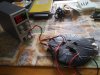
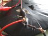
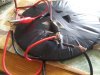
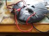
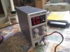
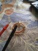
I have the pancake coil wrapped and tapped together to make sure it stays the way it should. I think I have all of the wiring correct so I'm not sure why it's not working. I'm using a DC power supply but it wont go above 1.4 volts.

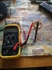
Also, to see if it is working I have a simple coil of magnet wire attached to a voltmeter which I am holding just above the primary coil.

I know it looks like a dangerous messy, trust me I plan on making this a more clean organized circuit once I get it to work. See all of the pictures to help get an idea of what I am talking about.

Do you gentlemen see something I don't?
 

Attachments

  • thumbnail_0327191056.jpg
    thumbnail_0327191056.jpg
    246.9 KB · Views: 167
  • thumbnail_0327191056a.jpg
    thumbnail_0327191056a.jpg
    169.5 KB · Views: 179
  • thumbnail_0327191056b.jpg
    thumbnail_0327191056b.jpg
    212.1 KB · Views: 173
  • thumbnail_0327191056c.jpg
    thumbnail_0327191056c.jpg
    296.3 KB · Views: 168
  • thumbnail_0327191056d.jpg
    thumbnail_0327191056d.jpg
    254.9 KB · Views: 172
  • thumbnail_0327191107a.jpg
    thumbnail_0327191107a.jpg
    284.3 KB · Views: 174
  • thumbnail_0327191107b.jpg
    thumbnail_0327191107b.jpg
    391.4 KB · Views: 166
I'm using a DC power supply but it wont go above 1.4 volts.
The coil current requirement is probably more than your power supply can provide, so the supply is limiting its output for safety. If the circuit isn't oscillating then there will be a heavy DC current through the coil.
 
the transistor should be mounted on a heat sink. the small coil of wire in the last two pics, is that bare wire or enameled wire? if it's enameled wire, did you strip the enamel off the ends so you could make the connections? your meter might not even read anything off that small coil, because the AC bandwidth of most DMMs is 1 or 2 khz. 1.4V @ 5A, and that's the current limit light that's lit? either the transistor is shorted, or the base is pulled high and the transistor is in heavy conduction. this type of circuit is not likely to oscillate if the voltage is turned up gradually, the power supply should already be on, and then connect the + wire to the circuit.
 
None of your connections are soldered so they might not connect.
 
I think #2 is the one to look for.
Reverse the connections to one of the coils & try again.
 
The coil current requirement is probably more th
an your power supply can provide, so the supply is limiting its output for safety. If the circuit isn't oscillating then there will be a heavy DC current through the coil.

The DC power supply can give up to 30 volts, but wont go above 1.4 volts. I hope that clarifies my statement! Thank you.
 
the transistor should be mounted on a heat sink. the small coil of wire in the last two pics, is that bare wire or enameled wire? if it's enameled wire, did you strip the enamel off the ends so you could make the connections? your meter might not even read anything off that small coil, because the AC bandwidth of most DMMs is 1 or 2 khz. 1.4V @ 5A, and that's the current limit light that's lit? either the transistor is shorted, or the base is pulled high and the transistor is in heavy conduction. this type of circuit is not likely to oscillate if the voltage is turned up gradually, the power supply should already be on, and then connect the + wire to the circuit.

Thank you for the response! Could you define what heat sink, and DMMs mean? Thank you!
 
Heatsink is a the big block of metal that lets the transistor transfer its heat to the air more efficiently. DMM is the digital multi-meter.
 
Part of the "trick" to this circuit is getting it to oscillate. If you have not tried it, when you apply the power do not slowly increase the supply voltage, rather use an On or Off approach. My guess is the transistor is not going into oscillation. When you try to measure the voltage on the pickup coil you are trying to measure AC correct?

Ron
 
I think what Al was saying is that the coil isnt oscillating and its pulling the voltage down on your power supply due to excess current.
You might have blown the transistor if it got over 150 degrees.
 
Part of the "trick" to this circuit is getting it to oscillate. If you have not tried it, when you apply the power do not slowly increase the supply voltage, rather use an On or Off approach. My guess is the transistor is not going into oscillation. When you try to measure the voltage on the pickup coil you are trying to measure AC correct?

Ron

I'm not sure...is the current produced in the secondary coil A/C or DC? I'd presume it's AC.
 
the transistor should be mounted on a heat sink. the small coil of wire in the last two pics, is that bare wire or enameled wire? if it's enameled wire, did you strip the enamel off the ends so you could make the connections? your meter might not even read anything off that small coil, because the AC bandwidth of most DMMs is 1 or 2 khz. 1.4V @ 5A, and that's the current limit light that's lit? either the transistor is shorted, or the base is pulled high and the transistor is in heavy conduction. this type of circuit is not likely to oscillate if the voltage is turned up gradually, the power supply should already be on, and then connect the + wire to the circuit.

Could you explain a bit more about DMMs bandwidths being mostly 1-2 khz?
 
Thank you for the response! Could you define what heat sink, and DMMs mean? Thank you!

Before tackling wireless electricity, do you think should do some studying about basics? Not trying to be cruel or put you down. But there are high level electronics engineers trying to do this and still having problems.
 
Most DMMs are made to measure the AC from mains electricity that is only 50Hz or 60Hz. Their readings fall off above 1kHz or 2kHz.
 
The coil out will be AC just like the coil transmitting. It will be the same frequency so enter what has been mentioned as to lower cost AC DMMs being average responding RMS indicating at whatever their upper frequency limit is. Above that frequency their response falls off. This is where a good scope is a nice touch.
I'm not sure...is the current produced in the secondary coil A/C or DC? I'd presume it's AC.

Ron
 
Your power supply is a 0-5A supply, so it is current limiting if it sees too low a resistance (too high current). You cannot raise the voltage because of this, the power supply is limiting the voltage so the current does not exceed 5A (5.16A in your case).
If the power supply allowed you to raise the voltage, the current would also increase, which is not possible with the power supply due to the current limiting.

Even if the coil is oscillating, the current is too high.

Of course, if you have something wired wrong, or a bad component, that could be shorting out your power supply as well.

Notice in the video that he is using a battery which can supply high currents, probably like 20A for short periods of time. Finally, you definitely need a heftyheatsink for the transistor. Without one, you can blow that transistor within seconds due to high heat buildup
 
The coil out will be AC just like the coil transmitting. It will be the same frequency so enter what has been mentioned as to lower cost AC DMMs being average responding RMS indicating at whatever their upper frequency limit is. Above that frequency their response falls off. This is where a good scope is a nice touch.


Ron
Is there a DMM you would recommend?
 
Your power supply is a 0-5A supply, so it is current limiting if it sees too low a resistance (too high current). You cannot raise the voltage because of this, the power supply is limiting the voltage so the current does not exceed 5A (5.16A in your case).
If the power supply allowed you to raise the voltage, the current would also increase, which is not possible with the power supply due to the current limiting.

Even if the coil is oscillating, the current is too high.

Of course, if you have something wired wrong, or a bad component, that could be shorting out your power supply as well.

Notice in the video that he is using a battery which can supply high currents, probably like 20A for short periods of time. Finally, you definitely need a heftyheatsink for the transistor. Without one, you can blow that transistor within seconds due to high heat buildup
Thank you, that was a terrific explanation. I understand the situation more now.
 
Thank you, that was a terrific explanation. I understand the situation more now.
Actually my first choice would be to look at the output coil on a scope. Less having a scope any AC True RMS responding meter which covers the frequency range (bandwidth) of whatever that oscillator runs at. My last and cheapest DMM would be an average responding RMS indicating DMM which should at least tell you if something is there. Everything about this simple circuit hinges on it oscillating. If the applied voltage is slowly increased there is a possibility the transistor will conduct, be saturated, act like a switch and get hot or simply burn up. That is why several post ago I mentioned applying 12 volts On or Off.

Ron
 
Status
Not open for further replies.

Latest threads

New Articles From Microcontroller Tips

Back
Top