philba said:
What is the reading between the 154's Vcc and Joystick ground? also, what is the reading between the 154's gnd and joystick gnd when seperated?
-Positive probe on '154 Vcc, Negative on joystick ground: 5.11V (new circuit ground not connected)
-If ground of new circuit is connected to joystick ground: 5.11V
-Between Vcc, and new circuit ground (not connected to joystick ground), 2.52v
LEN:
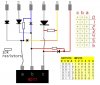
I have reconnected circuit ground to joystick ground, and powered the Hex Ic with 5+ from joystick as stated. I have connected each LED in series after the hex output and into y1-y6 inputs as per your diagram on pg4. I get similar results to previous test:
Gear1. just y1 led lights up
Gear2. just y2 led lights up
Gear3. just y3 led lights up
Gear4. just y4 led lights up
Gear5. y5 lights up as S3 is activated, (mechanically, S3 activated first, then S2, to make the combination)... as soon as S2 is switched too, y5 led light turns off, and y6 LED turns on!
Gear6. y6 does not light up, nothing happens at all.
VOltage test across LEDS:
Gear1: Engaged: -1.13V Disengaged: +3.10V
Gear2: Engaged: -1.17V Disengaged: +3.40V
Gear3: Engaged: -1.10V Disengaged: +2.70V
Gear4: Engaged: -1.15V Disengaged: +3.10V
Gear5: Engaged: +3.25v Disengaged: +3.29v
Gear6: Engaged: -0.02v Disengaged: +0.02v
Gotta do some other work now, see if I can do the other resistor circuit a little later this evening.