Continue to Site

Welcome to our site!

Electro Tech is an online community (with over 170,000 members) who enjoy talking about and building electronic circuits, projects and gadgets. To participate you need to register. Registration is free. Click here to register now.

  • Welcome to our site! Electro Tech is an online community (with over 170,000 members) who enjoy talking about and building electronic circuits, projects and gadgets. To participate you need to register. Registration is free. Click here to register now.

illogical transistor behaviour at voltage controlled amplifier and clipping

Status
Not open for further replies.

Fluffyboii

Active Member
1662665661302.png

I have build two identical versions of the circuit above on the same board. First VCA works and I can adjust it for both logarithmic and linear CV response to have no output at 0V CV. The second is working at linear response yet it can't shut down the input signal at log response. What I mean by it can't shut down the signal is: Because this is an voltage controlled amplifier it needs to have 0V at output when correctly biased with 0CV input. The second VCA does work at Log response but no matter the bias pot it always lets input pass through a bit.

Logically I checked the voltage differences between these two circuits to find out what is wrong with the second one. Turns out all of the check marks are the same when Bias is turned all the way down. Only difference is at the ":(" mark. The voltage at the collector of PNP transistor doesn't response like the first one. I used BC548 and BC558 for these. When I found that BC558 of the second VCA is acting weird I changed it with another one and another one. I tested like 5-6 different ones. I also tried changing BC548 with no avail. Because at the 2nd VCA the voltage at 1st pin of the LM13700 is not getting as low as the fist one the signal keeps passing through. I tried changing the ICs, I tried changing R18 with 475 instead of 222. I basically checked everything yet find a problem that would cause the issue.
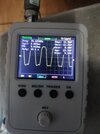
View attachment 138497And there is the thing above. Output is always the scaled version of the input but it is CLIPPED from the top for NO reason. I tried decreasing input signal volume with a voltage divider and nothing changed. At both VCAs and all of the CV response settings the signal has a positive voltage offset for no reason and I think as a result it clips from the top only. Since this issue can be only happening from the LM13700 I obviously checked all around it. I just can not find a reason. I don't know why voltage controlled amplifiers are this problematic.
 

Attachments

  • 1662666417281.png
    1662666417281.png
    6.5 MB · Views: 189
Are you sure R3 is the correct value?? With 2K feedback (R3) and 100K input, the output should vary just 1/50th as much as any input...

The positive input should be at approximately 1/50th of the positive supply also.
There are two 1K resistors in series for feedback (R3). And all connections seem right. I need to check it more. Looks like there is a bad solder joint under the 1K resistor and multimeter doesn't check it as connected with inverted input. That would explain inconsistency.
 
Last edited:
rjenkinsgb I checked the Op Amp output and it is sitting at -6.8V no matter the inverting input voltage. Inverting input side acts normal which is added voltages from Freq Adjust pot and CV input. Interesting thing is that non inverting input which should stay at a low positive voltage around 0.25V is sitting around -1.6V. This doesn't makes sense because I can clearly confirm the resistors connections. And non inverting input thats connected to +12V and ground via 100K and 2K resistor divider can't get negative voltage. Nothing about it makes sense. I tried different Op Amp and the result is the same.

It is oscillating by itself right now. This oscillation doesn't happen when amp bias is driven by another circuit and everything works when I do that. I removed resonance pot and it kept on oscillating. I can change its frequency with resonance pot though.

I removed the connection of the 100 ohm pot from the IC1-A thinking it was pulling it low but that made the output dip even lower to -11V

I decided to destroy all of it. And noticed that 2K feedback resistor was connected to positive input pin via some stupid wire lapping on top of it.
 

Attachments

  • IMG_20220915_011022.jpg
    IMG_20220915_011022.jpg
    1.5 MB · Views: 165
  • IMG_20220915_011039.jpg
    IMG_20220915_011039.jpg
    1.5 MB · Views: 157
Last edited:
It turns into a sine wave-ish form on all outputs and I can get it in weird shapes but it is not the perfect operation I achieved when I connected the amp bias pins to another circuit. I tried that again with same configuration and it burned another LM13700. The fact that same things bring different outcomes in electronics always amaze me. But hey at least I got outputs now even though all outputs act like low pass filters for some reason.
 
I fixed the second VCF design. It turns out I used 4.7K instead of 47K as feedback pulldown resistor and I burned the 100K pot when I connected the transistor backwards. So I replaced those and resonance still didn't work. Replaced the LM13700 and it started working as it should. Looks like that LM13700 lost one of its OTAs. This makes 3 dead LM13700s and 3 working. I need more. State variable circuit looks like it will never work as it should. I saw it work when I biased the LM13700 with the other circuit including the resonance as I mentioned but that did not happen second time. I guess I will order more LM13700s for now and also look for designs that does not use it. Such a fragile component.
 
Status
Not open for further replies.

Latest threads

New Articles From Microcontroller Tips

Back
Top