Continue to Site

Welcome to our site!

Electro Tech is an online community (with over 170,000 members) who enjoy talking about and building electronic circuits, projects and gadgets. To participate you need to register. Registration is free. Click here to register now.

  • Welcome to our site! Electro Tech is an online community (with over 170,000 members) who enjoy talking about and building electronic circuits, projects and gadgets. To participate you need to register. Registration is free. Click here to register now.

Identifying laser sensor component

Status
Not open for further replies.

supersonicman

New Member
I'm not sure if this is the right section to post in but I'm looking for some guidance on what type of part this is so I can do more research.

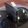
This came out of a huepar laser sensor for a laser level like you would find at a home improvement store.

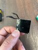
The front has a field of wires going horizontally, split into two fields, above and below the middle line. It detects when the laser level is hitting above, below or right on the line.

There are three connections at the top that I believe are: (+) for top field, (-) ground, (+) for bottom field. There is also a connection at the bottom that is ground as well. I assume the circuit measures the difference in voltage generated by the top and bottom fields.

The dimensions are about 1.25" x 1.25".

I would like to know what type of component it is so that I can start my research and design a custom circuit using this.

Short of identifying the part as a whole. Would anyone know what type of wire like the ones in this sensor would generate a signal?
 

Attachments

  • IMG_2763.jpg
    IMG_2763.jpg
    84.6 KB · Views: 246
  • IMG_5957.jpg
    IMG_5957.jpg
    48.6 KB · Views: 238
Looks like a small solar cell to me.
Agreed, just two sections with common negative and separate positive connections.

Directly comparing the two output voltages will show how well centred (or not) the beam is on the mid point of the two cell sections.
(The "wires" on the surface are the cell electrodes, that connect to the silicon layer, the active material)

It looks to be a low cost equivalent of a position-sensing or segmented photodiode such as this:
 
Thank you everyone. This gives me a good start but now I'm going to have to learn about solar cells which I know nothing about. :)
 
I worked in the industry doing research. Photocells operate in either the photovoltaic mode or photoconductive mode.
When you hold the cell at 0V, which is known as Jsc or Isc, the current output is proportional to intensity. For a solar cell, the negative bias line should be flat for a good cell. Another datapoint is Voc or voltage open circuit. This is when I=0.
When people want to generate power, there is an operating point call Jmp or Imp. This is where the power is maximum.
J is current density e.g. mA/sqcm and I is current of say 10mA. The sun at AM1.5 Global spectrum is 100 mW/sqcm
Solar cells have a spectral response. The AM1.5 global spectrum. Each Solar cell material has it's own spectrum. It's modified slightly by adding an AR (anti-reflection coating).

Your sensor is two split solar cells. When the beam is aligned between the cells, each is producing a small, but identical current.
 
Thank you, KISS. I follow what you are saying. I will delve deeper into this soon. I was not aware that there are different cell materials designed for different spectrums. I'm sure this will be important to me given that I'm working with green and red lasers.
 
Here https://www.researchgate.net/figure...of-several-different-materials_fig1_258717378 is a good graph showing the ty[es of material and spectral response (QE or quantum efficiency) curves. You can integrate these individual curves with the AM 1.5 spectrum and actually calculate the current at 0V.

Your detector, whatever it is, has a unique response at a given wavelength. To get there one takes a white light source and sends it through a monochometer to get a slice of light. This light is thermally measured and quantified. With a quantified amount of light, the QE of a test cell can be measured.
 
Status
Not open for further replies.

Latest threads

New Articles From Microcontroller Tips

Back
Top