Continue to Site

Welcome to our site!

Electro Tech is an online community (with over 170,000 members) who enjoy talking about and building electronic circuits, projects and gadgets. To participate you need to register. Registration is free. Click here to register now.

  • Welcome to our site! Electro Tech is an online community (with over 170,000 members) who enjoy talking about and building electronic circuits, projects and gadgets. To participate you need to register. Registration is free. Click here to register now.

Help identifying component

chrisdiyer

New Member
Hey all. I am attempting to repair my mom and dad stair chair lift after the cord got caught up in the gear and did some damage. Now when you plug the chair in it starts going up on its own. Looking at the circuit board I can see one component that's obviously fried, but I'm not too familiar with a lot of different components and can't seem to figure out what it is. Assuming it's the same as the ones it is next to, it is a white cylindrical through hole component. I don't see any identifying markings on them though, with the exception of one with the numbers 2067 on it. If anyone has any insight on this I would really appreciate it.
 

Attachments

  • 20241122_000715.jpg
    20241122_000715.jpg
    1.8 MB · Views: 129
The damage caused by the cord might have affected other parts of the circuit. Inspect surrounding components, traces, and connectors for signs of overheating or physical damage.
 
Yeah, I figured too that there's probably more wrong than just the one component. Figured I'd start with the obvious one though. And I'll have to check the resistance on the other similar components when I get back to their house.
 
When you say "The cord" can yo confirm that itwas NOT a cable that was part of the stair lift. If it was not part of the stair lift then the damage must have been caused by overloading the motor. So the first thing I would find out is the type of motor. Is it a mains voltage induction motor, a series wound motor , a shunt wound motor or a permenent magnet motor. I suspect it is a permenent magnet motor which is controled by an H bridge. (Using power transistors of mosfets.) I suspect that some of the transistors or mosfets have failed short circuit causing the motor to run when not commanded to do so. If this is the case I would test for shorted mosfets or transistors in the drive circuit.

Les.
 
Please be careful as you try to fix this. Repairs of device that can injure humans is no DIY weekend warrior work. The fact that the cord somehow got caught in the gears is just one example of how a person can be injured, burnt or electrocuted. Make sure all overload circuits still work, fuses or other protection works, stop-limits work, ... also, like any vibrating or moving equipment, make sure all cord restraints and cable management systems are working. (Obviously they were not because the cord got caught).

Good luck, be safe and call a professional from the manufacturer if you have any concerns. These are essentially medical devices and the user has diminished capability to react if something happens bad while it's being used.

I don't normally want to sound overly cautious but stranding an immobile person on a set of stairs while their motorized seat starts smoking is a real possibility.
 
It's a resistor, you can see the spiral winding if you look closely and it is not like any of the white links so measuring those is not going to be of any help.

Unfortunately, there is no way of determining the value of it as all the colour bands have been burnt off.

You will need to find someone with the exact same model and look in it to find the value - asking the manufacturer is not likely to elicit any information but there is no harm trying that path.
 
Reading 1k on it its possible the resistor is fine tbh. You may want to put in one a little beefier tho.
Its different shape then the white things, I dont think its the same. Looks like a normal resistor.

Maybe look for the components (Id guess relays or mosfets) that control the motors direction and check the one for going up to see if its shorted. If not work backwards from there with what's controlling it.
 
Last edited:
IF the resistance was measured while still in circuit it still could be open circuit. It needs to be measured with at least one end disconnected from the PCB
Have you checked what type of motor is used in the stairlift and what its voltage rating is. This will help to judge whether it is controlled by relays or semiconducter devices.
Les
 
Its different shape then the white things, I dont think its the same. Looks like a normal resistor.
I think it's just the plastic case has burned away.

All the installed links labelled "WHT" are bridging points across a score on the PCB, presumably where it can be split between two units in some applications.
 
IF the resistance was measured while still in circuit it still could be open circuit. It needs to be measured with at least one end disconnected from the PCB
Have you checked what type of motor is used in the stairlift and what its voltage rating is. This will help to judge whether it is controlled by relays or semiconducter devices.
Les
Very good point


I think it's just the plastic case has burned away.

All the installed links labelled "WHT" are bridging points across a score on the PCB, presumably where it can be split between two units in some applications.
Yea, that is definently a possibility but I dont really see any melted goo under/on it and size wise its looks like its the same sizer or bigger then the white components already.

I think the color labels are for the wire colors, not the components.
If you see gray you see the gray wire. The white looks possible to all connect back to white wire. There is also a yellow and a brown that look to probably be related to the yellow and brown wires. All the way right you see more white, red, black labels with wires of that color in them. Also a white component being in a spot labeled brown make me consider its more to do with the circuit for wires.
 
Last edited:
I think the TS needs to provide more information for us to do any logical fault finding. If he would trace the circuit around the burnt component it would help. A picture of the whole PCB might give us some idea of how the motor is controlled.
He has still not answered the question about the "cord" being some external cord rather than some internal wire that is part of the stair lift.

Les.
 
The cord I spoke about is part of the lift, but is basically like an extension cord that runs inside the track allowing power to the seat while moving along the length of the track. The cable has a plastic connection of links around it that allows it to bend and move along the track as the chair moves, exactly like the wires on the power sliding door of a van.
 
Was the cable just 3 core mains or did it also contain control signal wires for fixed controls to call it from the top or bottom of the stairs ? If it did then mains could have been shorted to a control wire causing the damage. As it use a mains powered motor it is unlikely that the electronics deal with overcurrent situations. Is the large black thing on the board a relay or a transformer ? Is there a separate transformer in the stairlift to provide low voltage for the electronics ? What is the part number of the TO220 device at the left hand end of the large black thing ?
Les.
 
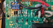
If one looks at the board picture, it looks like the entire right side of it was meant to be a "break away" board, but never "broken off". That is because there is a grove cut all the way down the board, under those jumpers. All the jumpers are just that, to make connection with the right side of the board to the rest of the board.
That said, the burnt component does look more like a resistor than a white jumper. Though the best way to measure it is with one leg removed from the board, if indeed the boards were originally meant to be separate, it is likely the measurement across while in place "may" be valid. Lifting one leg to measure it is best, but one does run the risk that it might break.
Did the fuse shown in the picture ever blow? Was the fuse tested? That burnt resistor is close to the terminal strip that has the white/green stripe wire going to the fuse. Now if the fuse was blown, it is not likely the chair would move in either direction. Whatever cooked the resistor may have damaged other components, but I don't think this board is what actually drives the motor. There has to be some other motor interface I would think? Unless there is a lot of circuits under that grey cover like area.
In this picture, it clearly shows a resistor type of device in that burnt position:

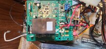
Also, this image (upper right) seems to follow the labels on that board, the forward/reverse switch seems to be wired to that top right terminal strip, and possibly the burnt resistor:

Capture.JPG


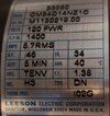
Also, this manual seems to be for an updated version of that board, with schematics...
 
Last edited:
The large black box on the board is a relay. I can see another board underneath that I'll have to remove a couple things to try and see. The cable contained 7 smaller wires, some of which do go to fixed controls. And in that top right diagram the spot listed as S2 that sits in line with that burnt resistor is where the fuse is wired to, and that fuse had been blown. The lift still moved up on it's own both with the fuse blown and after I replaced the fuse.
 

Latest threads

New Articles From Microcontroller Tips

Back
Top