Continue to Site

Welcome to our site!

Electro Tech is an online community (with over 170,000 members) who enjoy talking about and building electronic circuits, projects and gadgets. To participate you need to register. Registration is free. Click here to register now.

  • Welcome to our site! Electro Tech is an online community (with over 170,000 members) who enjoy talking about and building electronic circuits, projects and gadgets. To participate you need to register. Registration is free. Click here to register now.

Identify SOT23 device. marking is 1K

Status
Not open for further replies.

fastline

Member
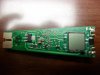
Quick story, this is a small, battery operated micro controller for a single motor load. There is 1.3V being lost between the battery and the motor and so the nominal voltage of the battery is 3.6V but if it is dropped to just 3.3V, the IC will initiate a slow shut down sequence probably thinking it is out of power and needs to maintain enough to turn on the charger transistor.

I went through most components trying to find voltage drop and this one SMD component came up on the radar because it is losing .8V. Now, if it is a diode, I get it, but if it is a transistor, that V drop is a bit excessive. My in circuit diode testing has not proven this to be a diode yet so I thought I would ask.

My thought is that the micro controller is monitoring the battery voltage and when the actual bat voltage is say 3.3V, it will think it is much lower and start shutting down. I really think there is either a leaky component or something with high resistance causing the controller to see lower voltage. Or I guess maybe the controller is bad. The IC is WAY too small to test without making some testing devices. Looking for the easy fix first.


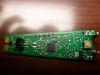
URCH - I disconnected the load (motor) and the controller now outputs full battery voltage to the terminals. I am not yet sure what that is telling me. Current goes up, resistance increases? Motor load is excessive? the battery pack is 800mah, 3.6V and motor draw is 1.25A. I did inspect the motor for shorted commutator, etc and all looked real good.
 
Last edited:
I've got alot of old circuit boards with SOT23 packages marked " 1K ", they are all NPN transistors. That doesn't mean yours is a transistor though (although it is quite likely) as manufacturers just seem to pick random numbers for SMD parts.
Sounds like the motor is taking to much current, can you try a different one.
 

Attachments

  • TR-1K.jpg
    TR-1K.jpg
    1.2 MB · Views: 414
I agree with you that it seems the motor might be the issue but I am a bit puzzled why the motor would be doing that. I have another assembly I might be able to rob the motor from.

Regarding the motor, this motor has capacitors mounted in the rotor for each (3) of the windings. I checked to make sure the commutator was not shorting across, etc. I notice that the motor is showing about 0-.1 ohms in the windings and usually I find DC motors to have a bit higher resistance. Any other thoughts to prove the motor bad? I do agree that the motor might just be the issue here. I just cannot really find much wrong with the control circuit and I felt the 1.25A was a little excessive.
 
0.1 ohms seems a bit low, it might have shorted windings.
Does the motor turn freely without any resistance ?
Worn or dirty bearings often cause excessive current draw.

I would try your other motor, then you can narrow the problem down to either the control circuit or the motor.
 
Yeah, I would expect maybe 2-8 ohms on the coils. The bearings are a special design that are basically just a floating brass assembly and I did not really detect excessive drag on them but I might just try lubing them. Because the circuit seems to trip out right when requesting inrush for the motor, I suspect of the motor is bad, it is the windings and not the bearings.

it might be good to point out that the manufacturer specs 100min of run time for this assy. As is, that is not possible because I am pulling 1.25A on an 800mah bat so that would really only be about 45 min at best the way it is now.

I did find that the circuit would drop down to about .9A and would always slowing correct itself with higher motor speed and increased current. that made me think it was supposed to pull 1.25A
 
Last edited:
Well, I swapped for another known good motor and the motor tests the same with very low resistance and again, the controller will not start the load. think the IC could do this or do they usually work or don't? Really puzzling since there are not many components in this thing and it acts like it just does not want to push enough current to get the load started. The motor is free as a bird.
 
Well at least you know the motor is ok.
Could you post some HI-RES pics of the controller.
 
We need to see the board really, but the sot23 device (if it is a transistor) should be a BC848B, the pin-outs are the same as the photo that SYE has sent you. You need to check that transistor for short/leakage with a suitable meter, but disconnect the motor first to avoid false readings. The small caps on the motor are just interference suppressors and should be ok. If the transistor checks ok then its probably the I/C.
 
Here are the pics. The one switch button is the on/off button, the 3 pin plug is the input from the battery, and the contact pads to the left of it are for the DC power supply input.

The two tall arms by the switch are to connect to the motor load. The LCD just monitors the battery life I believe (always showing low which is concerning) and has an LED under it that lights up when running.

Pretty stupid simple circuit. Curious what you guys think of it! I am baffled.. I have never heard of ICs failing like this. I thought they either worked or didn't


If these do not have high enough resolution, let me know. I am on my lowest setting. I have 2 more to go but are usually difficult to load to forums so I rarely use them.
 

Attachments

  • SDC11250.JPG
    SDC11250.JPG
    1.8 MB · Views: 294
  • SDC11251.JPG
    SDC11251.JPG
    1.8 MB · Views: 281
Last edited:
I agree with you about the microcontroller, if the LCD is working ok then it's probably alright.
I'm a bit confused about the part marked " 25M " , if it's a transistor then it doesn't appear to have it's collector connected to anything, if it's a diode then it's not connected in the way I would have expected.
Your battery pack appears to have a sense connection, this could be faulty, have you tried a different battery pack ?
Could you check the voltages I've marked on the board.
 

Attachments

  • SDC11251A.jpg
    SDC11251A.jpg
    1.6 MB · Views: 285
Will do. I have testing this circuit with another battery pack as well as our lab power supply to monitor current and voltage drop. Even with the lab supply, it would not start a load reliably until I boosted it over 4V. The battery pack is 3.6V. the wife also mentioned it seems to run slower than it did when new which is inline with reduced voltage to the motor.
 
bat voltage - 4.0V
A - 3.0V
B - 2.7V
C - 3.5V

These are all with the circuit turned on but no load attached. I cannot get the load started with just the bat. I have to start it with the charger and then remove the charger and difficult to do unassembled but if that is what it takes, I will find a way. 5
 
This is the voltage to base\gate of the big transistor (I can't see any markings on it but because of its configuration I assume it's an NPN bipolar) next to the power switch, having 3 volts there should mean that your motor would run and if it doesn't I would suspect this transistor. However if you reckon it runs ok with the charger connected I'm a bit confused. It should work.


The part marked " 25M " is a Voltage reference. This should read 2.5 volts. Having 2.7 volts there may be why the micro thinks the battery voltage is a bit low.


I had thought that this was the sense output from the battery, but I'm not sure now, it seems low though.


You could try replacing the voltage reference with something like a 2.0 volt zener to fool the micro, might work, might not. I'm running out of ideas.
 
I think the charger works because it charges at a higher voltage. I will try to do some voltage testing with the charger plugged in
 
As a quick and dirty test to see if the voltage reference is faulty solder a resistor in parallel with it, the value isn't critical, 4.7K - 10k should do the trick. Pick a value that will bring the voltage on pin 19 down to less than 2.5 volts.
 

Attachments

  • SDC11251B.jpg
    SDC11251B.jpg
    1.5 MB · Views: 272
I installed a 4.7K across these pins and test showed exactly the same performance. Failed to start the load and battery indicator still showing the voltage to be low on the LCD when it is not..
 
Well, figure this one out - The battery pack is a 3 wire system so it also has a thermal sensor mounted in the pack system. It was showing continuity when cold and I figured it should open when warm. I reassembled the device and out it on the charger. It now WILL run cordless on the battery and the battery indicator does show full charge so I think I am on the right track BUT the battery gets HOT. Like 130*F when charging. I think it is supposed to get a pulsed charge or at least kill charge at a certain temp. I am now wondering if the thermal sensor is an issue?

Thoughts? this is a (3) AAA NIMH pack. Nothing that can not be made in a few minutes but in testing, the pack did not show to be a problem.
 
The sensor is probably a thermistor, it should read high resistance when cold, the resistance should decrease as it warms up. I doubt that it would be working like a switch and going open circuit as it gets hot, that just wouldn't make sense (pun intended).
If the sensor was faulty it could stop the battery from ever charging which would explain alot. I thought you had tried a different battery pack ?
 
It has a proprietary pack in it. I am pretty confident the batteries are good through some testing but I will have to find out more about the thermal switch or temp sensor. There are no model numbers on the pack to trace it but I am sure most of these sensors are the same. Maybe the RC crowd would know about them?
 
Status
Not open for further replies.

Latest threads

New Articles From Microcontroller Tips

Back
Top