Continue to Site

Welcome to our site!

Electro Tech is an online community (with over 170,000 members) who enjoy talking about and building electronic circuits, projects and gadgets. To participate you need to register. Registration is free. Click here to register now.

  • Welcome to our site! Electro Tech is an online community (with over 170,000 members) who enjoy talking about and building electronic circuits, projects and gadgets. To participate you need to register. Registration is free. Click here to register now.

IC 555 duty cycle

Status
Not open for further replies.

mhar

New Member
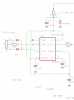
I'm using a 555 timer to generate a pwm signal to drive a LED driver chip.

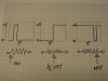
It all works except on dim the LED is still slightly on, pwm pulse is still there but shows on a scope as a spike.
I've tried germanium diodes and different C's but you don't get full 0/100% duty cycle.

Maybe another device is the answer, PIC Processor or something.
I'm a bit tight on space in the light fitting.
 

Attachments

  • pwm555.png
    pwm555.png
    10.6 KB · Views: 1,854
Put a cap across (parallel) with the LED. Then the very short pulse will produce a smoothed voltage lower than the LED turn-on threshold, so you will get PWM right down to zero (as far as LED brightness goes).
 
Thanks for all the answers.
I'm going to try the revised PWM Signal Generator.

just to clear up a few points:

IC555 pwm does not directly control the LED instead it's applied to a control pin on a driver chip.
The driver chip pulses the high power LED to set the average current@350ma.
The IC555pwm gates the driver with a variable pulse width - this sets the brightness.
 

Attachments

  • IMG_1356.JPG
    IMG_1356.JPG
    967.7 KB · Views: 1,832
Status
Not open for further replies.

Latest threads

New Articles From Microcontroller Tips

Back
Top