Continue to Site

Welcome to our site!

Electro Tech is an online community (with over 170,000 members) who enjoy talking about and building electronic circuits, projects and gadgets. To participate you need to register. Registration is free. Click here to register now.

  • Welcome to our site! Electro Tech is an online community (with over 170,000 members) who enjoy talking about and building electronic circuits, projects and gadgets. To participate you need to register. Registration is free. Click here to register now.

i want to buld my own CT

Status
Not open for further replies.

studyete

New Member
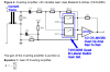
I would like to build a current transformer with the following specification...

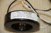
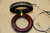
TD76V DC immune Current Transformer
*Rated current: 80,120Amp
*Dimension (I.D.XO.DXHeight): 12.9X37.5X14mm
*Safety approval: TUV
*Max rated current at 1ohm:330A
*Accuracy Class 1 Current Transformer

but the problem is, i do not have any idea how to start. can any one help please?
 
You should find some useful information in this link and subsequent links.

Attached are a few images of a 200 Amp CT including an open view. You may want to note the secondary winding consist of parallel windings using two lengths of magnet wire.

While the CT example in my photos has a plastic enclosure it is not necessary as the coils can be wrapped in a cloth tape and dipped in epoxy. Using some Google Skills the formulas can likely be found.

Ron
 

Attachments

  • Coil 1.jpg
    Coil 1.jpg
    154.7 KB · Views: 384
  • Coil 2.jpg
    Coil 2.jpg
    139.1 KB · Views: 275
  • Coil 3.jpg
    Coil 3.jpg
    258.1 KB · Views: 452
Last edited:
thanks for your reply reloadron, i need to make a CT under this specification.

the current transformer are scaled such that a voltage signal of no more than 1V peak-to-peak is present at the amplifier output when maximum current flows through the primary of the current transformer and the amplifier is set to minimum gain. For example, using a 2500:1 current transformer, a 68 Ω resistor.

If u can tell me which materials do i need to build this transformer than i might try. such as i need to know the required wire parameters and winding time i.e how much turn of the wire etc. also in your picture, what is the white and black wire for?
 
What amplifier are you talking about?

As to a current transformer a CT is a current ratiometric device. The primary for example in the images I posted the main current carrying conductor passed through the center, the secondary is the black and white wires exiting the housing. The wire turns you see are the secondary in the image. In the example a primary current of 200 amps would yield a secondary current of 5 amps. That 5 amps depends on what is known as the burden resistance. I suggest you read up on burden resistance as it applies to current transformers. Remember a CT is a transformer used to measure current. Voltage does not figure into the basics of a CT. The output is expressed in current and is proportional to the input current (primary / secondary).

If I place a resistor across the secondary of a CT then the voltage drop across the resistor will be proportional to the secondary current of the CT which is proportional to the primary current. In the case of my 200:5 CT if the primary current was 100 Amps AC RMS the secondary current will be 2.5 Amps AC RMS. If I place a 1 ohm resistor across the secondary the subsequent voltage drop will be 2.5 Volts RMS or 2.5 * 1.414 = 3.535 Volts peak.

Finally is this a homework assignment or school assignment?

Ron
 
I'm trying to build this atmel.com/dyn/resources/prod_documents/doc2566.pdf. It is an AVR atmega88 based energy meter. I'm unable to find the current sensor in my country, this is an university level project i'm doing. There is a circuit diagram provided in the pdf. I also have think about to use shunt sensor as current sensing and voltage sensor. But i do not know how to build shunt and voltage circuit in the existing diagram so that it can replace T1 and T2. If i can send the same data with shunt and voltage sensor, it might solve the problem of building the current transformer.
 
JimB, I don't know anything about CT, I thought i would get ready made CT from market so i would not have to worry about making one and i also no need to understand this. I just assemble the parts according to datasheet provided by AVR465. But when i have found that i do not have CT in market here, i went to the website copied the text under TD76V and pasted here.
 
OK, if you look at the data sheet and AVR465 data pay attention to page 7 and look at the drawing. We see the CT with the secondary across Rshunt labeled as RS. Back to my earlier post these would be the Black and White wires you questioned and the CT output. The voltage drop is passed to an amplifier with the gain of the amplifier controlled by the AVR (PIC Chip). They use a very common CD4066 quad bi lateral switch to do it. The CT in question has a 2500 : 1 current ratio so a current in the primary of 2,500 amps results in a 1 amp secondary current. You need to understand how the operational amplifier gain is established at this point.

It's not just about the CT you choose to use. It is about amplifying the CT output current across the Rshunt (RS):

Shunt resistor RS and the current transformer are scaled such that a voltage signal of
no more than 1V peak-to-peak is present at the amplifier output when maximum
current flows through the primary of the current transformer and the amplifier is set to
minimum gain.

Any number of current transformers can be used or as you began the thread with, make your own.

Ron
 
Hi Studyete,

Here is a link to a company that is international. They will also custom make CT's. They may have something on the shelf that you could use also.


Hope this helps.

Inquisitive
 
Understand Reloadron, So whatever CT i use, i have to adjust RS and A in such a way so that i can have 1V at amplifier output. But i'm little bit confused about the equation, as you said if i use 2500:1 that mean 2500 am goes to primary 1 am will go secondary, than in equation, what is 10A rms? used as I max current?


Question to all: any one know the market for buying electronics parts in new York? pleas let me know the addresses if any one know.
 
halo Reloadron, another thing is came to my mind, if my goal is to have 1v peak to peak output from amplifier, U3A and U3b, (m not sure whether both amplifier must give the same output or not) what if i build a shunt sensor so that the same gain i get from the amplifier? isn't it possible?
 
Inquisitive provided a good distributor link. As to New Your and NYC area, here in the US I generally use distributors like Allied Electronics, Digi Key and others. Let me ask you something. What is the Maximum current you expect to measure? While the original transformer mentioned (TD76V) was a 2500:1 ratio the maximum current is only about 330 amps. If you can tell me a maximum current we can likely work much better from there.

Also, as to the value(s) of Rshunt, t5his needs to be watched carefully. Remember I mentioned "Burden Resistance"? Depending on the CT we can't just use any resistance.

I have to get going to work here so later I'll post more info if I have a quiet day at work or when I get home from work.

Ron
 
I've asked my instructor about this, he told me that you can't say how much current flows in load line. Electricity in Bangladesh is 220 Volts, alternating at 50 cycles per second. So, i want to measure current that uses in house from this line. In a house, there are many objects that uses current, so i don't know the max current that will be use in house. Another thing i can do is to demonstrate a meter which will use a 40 or 100 watt bulb only. I think there will not much current will flows from the wire which will connect to 220 volt 50Hz line.

I understand that we just can't use any RS to get 1 volte at the output for different CT. I might ask my instructor how to choose or calculate the RS value for this. I think at equation 8, A is fixed from op-amp. Ration of CT will give N, and i told at my precious post that I don't understand what is I max, if i max is total current used by load, than i'll use 40 or 100 watt bulb only.

Also i have asked to let me know if replacing CT is possible with shunt sensor, because that would be easy i believe, I just have to change some part of circuit design.
 
OK, lets go over a few things and hopefully we can clear a few things up so you better understand. You are working from the AVR465: Single-Phase Power/Energy Meter
with Tamper Detection.
If you look at that document you will find the attached image that is seen on page 7.

The data for the current transformer used in the drawing can be found here and is listed as model number TD76V. Current transformers can have their specifications stated in a few ways but are always ratio devices. This particular transformer has a ratio of 2500 : 1. They also spell out a maximum current of 330 amps (Im : Max rated current). So the maximum current through the primary can never exceed 330 amps and the ratio is 2500 to 1.

Looking at figure 4 which is attached with a few notes we can start with the actual CT. The secondary of the CT is driving RS as a shunt resistor. The current flowing in the CT secondary will produce a voltage drop across RS and RS in this case is a 68 Ohm resistor.

Just as in the document let's assume we have a primary current of 10 amps on our CT. Since we have a 2500:1 ratio the secondary current will be 10 amps / 2500 = .004 Amp or 4 mA. This is RMS current. So we have .004 amp flowing through our 68 Ohm resistor which will produce a voltage drop of 68 Ohms * .004 Amp = .272 volts RMS.

Now they do something pretty cool here. They use 1/2 of a LMV358 Dual Ral to Rail Op Amp to amplify the output of the CT as a voltage. They also have a way to control the gain of the Op Amp. This is where the 74HCT4066 Quad bilateral switch comes into play. If you read the AVR document they explain how resistors are switched in and out to achieve a Low, Medium and High gain and specify the gains. The lowest gain being about 1.25.

Remember our 10 amps that gave us .004 amp through the 68 ohms for a voltage of .272? Well let's amplify that .272 * 1.25 and we get 0.340 Volts RMS. To get the peak value we multiply that 0.340 * 1.414 = 0.48076 Volts Peak and the Peak to Peak is now = 0.4876 * 2 = 0.96152 Volts Peak to Peak. There are a few ways to arrive at this number as can be seen in the AVR sheet but you should get the idea.

So in conclusion you can use any number of current transformers. The magic or trick becomes working with the CT ratio (keeping in mind the CT maximum current) and of course the Rshunt value.

If for example we used the shunt I posted pictures of earlier it was a 200:5 ratio with a max current of 200 amps. Since 200 amps = 5 amps this would be a 40:1 ratio. If we take 200 / 5 = 40 we get a 40 to 1 ratio. So now if we pass 10 amps through the primary the secondary current will be 10 / 40 = .250 Amps. We want a maximum voltage of .272 volts RMS so we get .272 volts / .250 Amp = 1.088 Ohms for our Rshunt. We know that .272 volts RMS will give us the peak to peak voltage we want.

The coding of the AVR does the rest. Has this helped?

<EDIT> Using the 2500:1 ratio for current we used a 68 Ohm resistor. Using a 40:1 ratio for current we used a 1.088 Ohm resistor. Think about it, that 2500 / 40 = 62.5 and if we multiply our 1.088 ohms by 62.5 we get what? Why 68 Ohms of course so I guess it really is all about ratio. :) </EDIT>

Ron
 

Attachments

  • AVR465a.png
    AVR465a.png
    55.5 KB · Views: 316
Last edited:
Quick question, What if we pass max 200 current through primary? The RS value will become much lower than (i actually calculated with 200A)? The way we arrive to the solution is to maintain 10A current at primary, what if current increase and pass at 20+A at primary? do i have to change the resistance of RS? What i'm understanding is that i can not add any equipment as load which need more current than 10A.
 
That would be true, if we read the AVR data it says:

A prototype built for 230V and 10A operation showed better than 1% accuracy over
a dynamic range of 500:1. With careful PCB design and following the guidelines
given at the end of this document the accuracy can be further increased. The meter
is easily configured to fit any other voltage and current settings.

The AVR prototype was designed around a maximum 220 VAC 10 Amp. The CT chosen was a 330 Amp maximum CT. The max current however is 10 amps because with the lowest gain settings and 10 amps we get that 0.96152 volts peak to peak. The reason for keeping the actual voltage into the Atmega chip at about a volt is because the Atmega chip reference voltage is 1.1 volts.

The fact that the CT in the example has a max current of 330 amps or in my example the CT max current is 200 amps really matters not. The Atmega example as drawn is designed for 10 amps maximum current. Think about Rshunt and the subsequent gain. The CT ratio, the value of Rshunt and the amplifier gain all determine the maximum readable current. Incidently at 220 VAC a load of 10 amps is 2.2 KW (2,200 Watts). While not very high that is considerable power for a residence load.

The value of Rshunt is fixed at 68 Ohms in the example. It does not change. If we reduce Rshunt to 6.8 Ohms the max current we could measure would be 100 amps. That assumes the CT can use a 6.8 Ohm shunt resistance. There are considerations all through the design that must be followed.

Ron
 
Last edited:
It's getting more clearer to me now. I have got a CT of 200:5 ratio. I think i can connect it with the load, but the problem is, i got one pcs, so what if i don't take the reading of neutral? My understanding is the T1 and T2 both same circuit, the mcu compare the current in both circuit and take the maximum value as result.


Remember our 10 amps that gave us .004 amp through the 68 ohms for a voltage of .272? Well let's amplify that .272 * 1.25 and we get 0.340 Volts RMS. To get the peak value we multiply that 0.340 * 1.414 = 0.48076 Volts Peak and the Peak to Peak is now = 0.4876 * 2 = 0.96152 Volts Peak to Peak. There are a few ways to arrive at this number as can be seen in the AVR sheet but you should get the idea

I did not understand where do u get 1.414 of 0.340 * 1.414 = 0.48076 and 2 of 0.4876 * 2 = 0.96152?

Another thing is our line is 230volt line, so i think that will change calculation for Rshunt for the CT of 200:5 as you did above?
 
It's getting more clearer to me now. I have got a CT of 200:5 ratio. I think i can connect it with the load, but the problem is, i got one pcs, so what if i don't take the reading of neutral? My understanding is the T1 and T2 both same circuit, the mcu compare the current in both circuit and take the maximum value as result.

I did not understand where do u get 1.414 of 0.340 * 1.414 = 0.48076 and 2 of 0.4876 * 2 = 0.96152?

Another thing is our line is 230volt line, so i think that will change calculation for Rshunt for the CT of 200:5 as you did above?

OK, let's think about what you mentioned. In a single phase AC circuit the current flowing to the load on the Line Side or Hot Side is the same current flowing through the Neutral or Return line. Let's say we have a single phase 240 VAC circuit and the load is a 2,400 watt heater element. I used a heater element as we want to keep this simple. Since P the power is equal to the Current * Voltage we can say 2400 watts / 240 volts = 10 amps. That same 10 amps flows to and away from the load Through the Line and Neutral so we only need to measure one line of the two. There is absolutely in this case no need for a second current sensor or in this case a second CT.

Remember earlier I mentioned a CT (Current Transformer) was a ratio metric current device? The line voltage has nothing to do with it at this point. It matters not if the line voltage is 115, 120, 230 or 240 volts. The line voltage becomes important when we want to calculate the power which comes later. So when you say:

My understanding is the T1 and T2 both same circuit, the mcu compare the current in both circuit and take the maximum value as result.

That would be incorrect. The MCU will look at the voltage on one channel and the current on another channel and then calculate the power. It will also do more math to calculate the watt hours or the kilo watt hours as necessary. All of this done using the code programmed into the MCU. Again, the line voltage does not figure into calculating the value of Rshunt, the current transformer is a current (not voltage) device or sensor.

So where did I come up with that magic number of 1.414? :)
For sine waves:
To calculate the RMS value of a sine wave, multiply the peak value by 0.707. The peak value is, of course, one half the peak-to-peak value. To go the other way, reverse the order of operations. That is, if you're starting with an RMS value, divide by 0.707 and then multiply by two to get the p-p value. Another way to convert from RMS to p-p is to multiply the RMS value by two square roots of two: RMS x 2 x SQR(2).

Or more simply, to convert from RMS to peak to peak voltage:

(RMS x 1.414) x 2=P-P

For example:

120vac x 1.414= 170vac
169.68vac x 2 = 339.36vac P-P

If I have time today I'll try to get an example with pictures but for now you should have enough to digest. I will also point out that we are only using Current Transformers for this exercise with the AVR chip. Normally I seldom use a CT anymore and prefer to use newer and better Hall Effect Sensors with built in amplification and nice linear outputs of voltage or current making things easier and generally more accurate. The same is true of how I measure the line voltage.

Ron
 
I have to read the sine wave part carefully again, but about the ct, it is written at introduction of their datasheet
This application note describes a single-phase power/energy meter with tamper logic. The design measures active power, voltage, and current in a single-phase distribution environment. It differs from ordinary single-phase meters in that
it uses two current transducers
to measure active power in both live and neutral wires. This enables the meter to detect, signal, and continue to measure reliably even when subject to external attempts of tampering.

so if i use single CT for both live and neutral wire, will there be any problem?
studyete-albums-ct-picture58636-ct-connection.html


https://www.electro-tech-online.com/members/studyete-albums-ct-picture58636-ct-connection.html

is this connection okay? if i use single CT?
 
Last edited:
Status
Not open for further replies.

Latest threads

Back
Top