Continue to Site

Welcome to our site!

Electro Tech is an online community (with over 170,000 members) who enjoy talking about and building electronic circuits, projects and gadgets. To participate you need to register. Registration is free. Click here to register now.

  • Welcome to our site! Electro Tech is an online community (with over 170,000 members) who enjoy talking about and building electronic circuits, projects and gadgets. To participate you need to register. Registration is free. Click here to register now.

I need help with troubleshooting Sony GDM-FW900 24” CRT

Hello, I am the first owner of the monitor. I reached almost every repair store in my area, but no one even wanted to hear about troubleshooting an old CRT monitor. At this point, I have been trying to figure it out by myself, but I have no idea where to start or look for.

I wish to know how to think and locate a failing component. I will put all my efforts to learn and contribute.
  1. It started with a bright and greenish picture upon starting a cold monitor.
  2. About 2 years ago, only on the cold boot, the screen started to occasionally flash with a green picture with retrace lines.
  3. About one year ago, when the screen was flashing on a high resolution I had to switch the input to only the OSD menu because in another case the screen would turn off and the diode would start to blink orange.
  4. At this point, I started to turn on the screen with 640x480 resolution to the moment when he will warm up.
  5. Always after the power station was turning on and off electricity, the issue started to progress. Basically, the electricity was cut off from the monitor a few times in a row in a very short period of time.
  6. After a few episodes like that, the screen started flashing red instead of green.
  7. After a few months, it was green and red in a similar proportion. The monitor had to be warmed up by switching INPUT 1/2 to calm him down.
  8. At this time I have decided to keep him turned on all the time. He was working from one electricity shutdown to another.
  9. After another episode with electricity, I wasn't able to power him on. I need to press the power button on and off for 20 minutes to finally succeed.
  10. At this point, the only way to power him on was by pressing power on and off and changing the inputs from the front panel. He needs to stabilize and I won't do anything he will turn himself off like in this video
  11. The last few times I was able to power him after heating his back with a hairdryer. When he was turning on he wasn't flashing red or green. He was warmed up.
  12. At this point, I have stopped trying to power him on. There is a big chance that I would be able to turn him on but in the long run, it's pointless.

I have to fix my friend.

From the observations.
  • When the monitor will luckily turn on there are absolutely no issues as long as he is displaying the picture. When the monitor will lose power or will go to standby mode it is not working and cannot be turned on.
  • When the monitor will somehow turn on it is flashing green, red, or both. It depends on the room temperature.
  • If he receives a high-resolution picture from a graphic card (higher voltage needed to operate) he is flashing green and red and goes to the standby mode and cannot be turned on again. He cannot stabilize
  • It was required to keep him on 640x480 dpi until he will warm up
  • If the back of the monitor was preheated with a hairdryer from the sides and turned on there is no green and red flickering and can instantly operate on higher resolutions with no issues. If he will luckily turn it on.
  • When he cannot be turned on and there is no graphic card connected to the monitor the led is green and goes to standby mode. There is no OSD menu displayed at all or green INPUT subtitles on the screen.
  • If he has a graphic card (first video input 1) connected, the monitor after a few seconds starts blinking orange - no light - orange no light infinitely. In the video below I am switching from INPUT 2 (no source) to INPUT 1 (VGA source). For BNC sources the same situation. There is no OSD menu displayed at all or green INPUT subtitles on the screen.

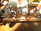
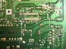
- I have dissembled him and could not find any burned, discolored, odd electronic elements.
- I couldn't spot any cold joints with a magnifying glass.
- I measured the output G board voltages upon turning on the monitor (green diode).
- I have corrected soldier joints around flyback
- Tube, Flyback, and caps are unlikely the issue (the guy who is having the same symptoms on the video had replaced every single cap across all of the boards)
- Something is shorting him heating up is not helping anymore

CN651
7V = 7V

CN650
STB5V = 5V
1W5V = 5V
ECO SW = 5V -> po chwili 3.5V
HTR SW = 4.9V
DGUSSW = 4.8V -> 0V
PWR SW = 5V

CN652
STBY5V = 5V
1W5V = 5V
+80V = ~15V for 1/2s -> 0V
+220V = ~90V-200V for 1/2s -> 0V
+12V = ~3.43V for 1/2s -> 0.04V
HEATER = 5V

CN653
+15V = ~1.36V for 1/2s -> 0.02V
-15V = ~2.43V for 1/2s -> 0.02V
+80V = ~3.8V for 1/2s -> 0V

CN653
H CENT H = ~4.3V for 1/2s -> 0V
H CENT N = ~6.3V for 1/2s -> 0V
H CENT L = ~7.2V for 1/2s -> 0V
+220V = ~15V for 1/2s -> 0V

- I have also measured the input on pins 1 to 9 on IC620 MCZ3001D SW REG CONTROL. They are not correct according to the Service Manual. I have voltages on GND and 0. The complete measurements in my playlist https://www.youtube.com/playlist?lis...rUeEXE58CKJpQU

First video from the playlist

At this point, I don't know where should I look for a failing component and how to proceed. If someone has an idea what should I check next and how it suppose to behave I would be grateful for any help. Please, I don't wanna hurt my friend, and it is hard for me to proceed on my own.
 

Attachments

  • GDM-FW900.pdf
    5.5 MB · Views: 122
  • IMG_1464.JPG
    IMG_1464.JPG
    3.6 MB · Views: 127
My first guess would be the CRT is worn out, and the auto-adjustment circuits are no longer able to adjust for it's loss of emission. You might try turning the G2 (screen grid) voltage up a little, as this 'may' give you a few more weeks use from it.

Such problems are common in Sony TV's, or any CRT set that uses auto-greyscale correction - on sets without it, you would already have binned it because of the crappy picture.
 
Hello! Thank you for the replay. Where I can locate the G2 voltage regulator to try that?
I am not sure if have I written precisely the problem.
When I was still able to turn on the monitor
- When his back was heated up with a hairdryer no green flickering, instantly perfect colors.
- When he wasn't flickering green/red instantly perfect colors.
No warming up and adjusting colors were needed. Perfect black at 20% brightness and 100% contrast.

Something is shorting him and refusing to power on.

PS: Is a faulty power supply might cause those issues?
 
Last edited:
Hello! Nigel Goodwin At this moment I am waiting for a DAS cable to connect the monitor to a computer (in order to lower G2 Voltage I need him) Meanwhile, I have performed some measurements around the switch voltage regulator on the power supply board. Could you take a look at those? I am concerned also about one resistor that is not present in the service manual and high voltage across 2 resistors connected to (1) V sense. My knowledge about CRT is marginal

G2 Voltage on A board = 0.00V

[G board (Power Supply)]


Measurements around IC610

C611 = 420V - (10) CATHODE but according to the Service manual it should be 376V

R643 = 0.0V
R629 = 0.0V
C639 = 9.3V
C648 = 14.8 V

R625 = 0.00V - should be 192V - (16) VG (H) (IC620 MCZ3001D SW REG CONTROL)

Those 2 resistors are on the red line going straight to (8) VC1 (IC620 MCZ3001D SW REG CONTROL)
R631 = 0.9V
R696 = 3.1 V

Out from VCC z IC610 - red line
R614 = 2.5V
C613 = 13.5V

C611 = 250V it is connected to (3) AC SEN IC610 (but in the Service manual it says it should be 86.2 V)

R620 = 0.0V
C643 = 0.15V
R621 = 97.0V

I don't understand what is going on with the R651 resistor, he is not present in any service manual
R651 = 73.0 V (photograph below)
IMG_1502.JPG


The leg of R651 is connected to (1) V SENSE and the voltage across resistors is
R651 and R621 = 402 V is connected to (1) V SENSE of (IC620 MCZ3001D SW REG CONTROL) but in the service manual is printed it should be there 1.7V

C645 = 2.2V (3) CT - OK - Service manual = 2.2V (IC620 MCZ3001D SW REG CONTROL)
C647 = 0.00V (6) TIMER - OK - Service manual = 0 V (IC620 MCZ3001D SW REG CONTROL)

Here, does it mean that C646 is failing and needs to be replaced?
C646 = 0.17V (7) SS - WRONG - Service manual = 4.5V (IC620 MCZ3001D SW REG CONTROL)
I don't understand why when I am touching with only one prob of the multimeter on the legs of C646 I have 2.7V readings (the 2nd probe is in the air, not touching anything)

C640 = 10.8V (10) VC2 - OK - Service manual = 10.3 V (IC620 MCZ3001D SW REG CONTROL)

C642 - 0.00 V
R625 - 0.00 V
R626 - 0.00 V
 
R651 is simply in series with R621, which is shown on the circuit. Presumably it was a later modification, and was probably shown in an update to the service manual - I imagine there were problems with R621? (like the special resistor was too expensive!), so they put two in series to make it even more unreliable (resistors in series like that are one of the most common failures in TV's).

Where are you measuring all these voltages from? - these are all on the fully live (dangerous) side of the power supply, and can't be measured with reference to the secondary side or chassis.

There also seems no reason to be messing about on the primary side anyway - unless you have proven the fault lies there?.

Stick to the 'safe' secondary side - and check voltages on socket CN650 - pins 1 and 2 should be 5V, pin 4 is the power switch, and should be high (5V?) when the set is switched to ON. If pin 4 is low, then the set is switched off.

If pin 4 is high, then you should be getting the +/-15V, +220V rails etc. on the other sockets - unless the PSU protection has triggered, Q653 and Q667.
 
Understood, so cool! Thank you, Sir. I am so grateful for getting back to me. I am doing my best to not harm myself and the CRT. My initial thought was that something is not functioning around IC620 MCZ3001D SW REG CONTROL since there is no voltage on 16 VG (H) 15 VS 14 VB

I wanted to measure voltages on pins of IC620 but didn't know where to put the negative probe so I left it for now.

I am going to measure voltages around Q653 and Q667. There is a C646 cap but the voltage on it is very low 0.17. I was thinking about replacing him (I have a few of them identical).

I have measured, values from the 1st post once again. There is no voltage +/-15, +220, etc. The monitor is turning on, green diode but no picture, no OSD. The measurements from the previous post are measured directly on the components.

CN651
7V = 7V

CN650
STB5V = 5V
1W5V = 5V
ECO SW = 5V -> 3.5V
HTR SW = 4.9V
DGUSSW = 4.8V -> 0V
PWR SW = 5V

CN652
STBY5V = 5V
1W5V = 5V
+80V = ~15V for 1/2s -> 0V
+220V = ~90V-200V for 1/2s -> 0V
+12V = ~3.43V for 1/2s -> 0.04V
HEATER = 5V

CN653
+15V = ~1.36V for 1/2s -> 0.02V
-15V = ~2.43V for 1/2s -> 0.02V
+80V = ~3.8V for 1/2s -> 0V

CN653
H CENT H = ~4.3V for 1/2s -> 0V
H CENT N = ~6.3V for 1/2s -> 0V
H CENT L = ~7.2V for 1/2s -> 0V
+220V = ~15V for 1/2s -> 0V
 
It's almost certainly nothing to do with IC620, or indeed anything in the primary side of the PSU. As the secondary voltages are coming up, and then disappearing, with 5V still on the PWR SW connection, it seems likely that the over volts protect circuit is firing. Check the voltages around Q667, if it's NOT triggered they should be about 4V on the emitter and base, and 0V on the emitter. If it is triggered, the emitter and collector will be around 0.7V - the two transistor form a latch, similar in operation to a thyristor (which is also a PNPN device).

Assuming it is triggered?, then if you have a scope check the ripple on C650, the 220V reservoir capacitor - as the feedback signal is taken from there, if the capacitor has dried out or gone high-ESR, there will be lot's of ripple on it, and this will cause the outputs of the supply to be excessive, so to prevent damage the protection circuit Q667/Q653 switches the PSU back off.

If you don't have a scope, then stick another capacitor in parallel with C650 - it doesn't need to be 100uF just for testing, but it must be 250V - anything above 10uF should be OK just to stop the over volts triggering, if C650 is duff.

Historically, for testing large capacitors in valve TV's (a common failure), we always used to have a suitable high voltage capacitor in the workshop fitted with wires to crocodile clips, so you could just clip it in place to check if any of the capacitors were faulty. Often such capacitors were multiple capacitors in a single can, and usually only one would have failed.
 
Understood, I am gonna do measurements right now. I have replaced C646 (2.2uF 50V) now I have voltage on him

C646 = 28V, the weird part is the monitor woke up and gave a screen with an OSD picture. But the picture was very bright with a greenish picture on it. I turned him off and was able to turn him on one more time. Now, when I turned on the monitor no change, but the voltage on C646 is present. But when I put a multimeter on C647 to measure voltage the monitor powered on again (only a few times).

I have replaced C646 again and noticed, the monitor power on the first try. Only once, again very bright. When he was heated with a hair dryer there was no over brightness.

I think the monitor was powered on because he was heated in this area.

Used to be C646 = = 0.17V (7) SS - WRONG - Service manual = 4.5V (IC620 MCZ3001D SW REG CONTROL)

Correct: now when I heat back the area for 30 seconds with the hair dryer he is always powering up very bright (I am turning him don't wanna harm him). Not sure how to locate which component needs to be heated (failing) and needs to be replaced.
IMG_1502.JPG
 
Last edited:
Again, WHERE are you measuring from? - I suspect you're still not making any kind of 'measurements' because you're not doing it correctly.

I'm rather dubious where this is going, if you don't even know enough where to measure from?.

Think of testing a battery with your meter - you put the red lead on the positive of the battery, where do you put the black lead? - in this case I suspect you're effectively connecting the black lead to an entirely separate device.

If you're measuring voltages on the secondary side of the PSU (anything to the RHS of the transformers and opto-isolators) you measure from chassis - BUT, you can't measure anything to the LHS of those components measuring from chassis.

To measure anything on the left hand of the PSU you MUST!! measure from the negative side of C610 (or any of the points that it connects to) - otherwise you're not measuring anything.

To expand the battery analogy - imagine you want to test the battery in your portable radio, so you connect the positive of the meter to the positive of the radio battery, but you're then connecting the negative of the meter to the negative of the battery inside your portable CD player.

This is the situation you're in - the radio is the LHS side of the PSU, and the portable CD Player is the RHS of your PSU - so you can't possibly measure anything.
 
I understand, I am measuring the voltage drop on components eg. red on one side of a cap and black on the other side of the cap. Same with voltage drops on resistors. I am not using chassis.

For probing IC620, black on negative C610 and probing with red (1), (2) etc
 
Any slightly bulged lids on e-caps, that's an obvious fault.

CN652 +80V = ~15V for 1/2s -> 0V
CN653 +80V = ~3.8V for 1/2s -> 0V

Either 80 V cap is weak or the load is too great.

1685911029816.png
 
The voltage across the series R656 will measure the charging current and maybe the steady-state load if it stays on long enough before some fault is detected.

1685911562751.png


Turning the brightness down may help reduce load.
 
Thank you Tony Stewart . I am just another idiot on the internet, again thank you for taking your time, I am trying my best to learn something and put in some work.

I put back the old caps. I think there was no problem with those caps.

Heating up the IC620 SW REG CONTROL from the back (the leg side) even for 10 seconds always makes the monitor power on.

I even took a cardboard shield covering the board except for the IC.

The brightness goes away after a moment, and the screen blinks green and is constantly red, after the moment when I put 640x480 video input it stabilizes and colors are back to normal, and after 10 minutes I can put a higher resolution. From this point, everything works fine to the moment, when the monitor loses power/signal (and goes stand-by).

There is some component that is probably failing because when the monitor is preheated (all of it) there are no wrong colors - he starts with perfect colors. Or is faulty IC620 can make green/red colors on the start?

Edit: I have not spotted a single cap across the boards that look odd or anything.
 
You're still ignoring everything I tell you, it's highly unlikely to be a fault on the primary side - what are the voltage readings on Q667 - that's the first thing you should be checking with the symptoms you have.

It's highly unlikely to be electrolytic capacitor failure in a Sony set, as they always used decent quality ones (in items of their own manufacture - different though in cheap Chinese sound bars they sold, where the Chinese fitted the usual crap ones).

But first you need to confirm if the trip is triggering or not.
 
Thank you Nigel Goodwin , i didn't want to upset you or be ungrateful, the protection was not triggered when I was turning on CRT.

The monitor is now turning on.

I have noticed that heating up IC620 powers on the monitor I think the 7 or 8 leg was responsible for that state. So I have replaced IC620 and the monitor is powering on every time but the screen is RED / GREEN.

I have noticed that shortly heating UP with a hairdryer back of pcb (not IC620) but closely around gives a proper picture for 2-4seconds (black background and this color input osd)

I have replaced 3 electrolytic caps around C645, C647, C646 but no difference

I think that there is something that killed IC and is doing this color problem (later CRT has proper colors after a very long time warmup and switching input 1 to input 2)

Any idea which type of component might be doing that, caps, res diodes? I don't know how to locate the component that is failing
 

Attachments

  • IMG_1502 - Copy.JPG
    IMG_1502 - Copy.JPG
    2.8 MB · Views: 97
Thank you Nigel Goodwin , i didn't want to upset you or be ungrateful, the protection was not triggered when I was turning on CRT.

You're not upsetting me, I just wanted you to do the most basic first test - something which you've still never done (or at least posted the results).

The monitor is now turning on.

I have noticed that heating up IC620 powers on the monitor I think the 7 or 8 leg was responsible for that state. So I have replaced IC620 and the monitor is powering on every time but the screen is RED / GREEN.

I have noticed that shortly heating UP with a hairdryer back of pcb (not IC620) but closely around gives a proper picture for 2-4seconds (black background and this color input osd)

I have replaced 3 electrolytic caps around C645, C647, C646 but no difference

I think that there is something that killed IC and is doing this color problem (later CRT has proper colors after a very long time warmup and switching input 1 to input 2)

Any idea which type of component might be doing that, caps, res diodes? I don't know how to locate the component that is failing

Most likely cause is the CRT, particularly when it's better after along warm up (the emission gradually improves as the CRT warms up).

Apply a greyscale test signal to the monitor, and check the signals on the three CRT cathodes and compare them.

PSU wise you might check the heater supply voltage for the CRT, which rather bizarrely is DC? - pin 9 of CN652. Heaters are normally 6.3V AC, so as it's DC should be about 6.3V DC instead.
 

Latest threads

New Articles From Microcontroller Tips

Back
Top