Continue to Site

Welcome to our site!

Electro Tech is an online community (with over 170,000 members) who enjoy talking about and building electronic circuits, projects and gadgets. To participate you need to register. Registration is free. Click here to register now.

  • Welcome to our site! Electro Tech is an online community (with over 170,000 members) who enjoy talking about and building electronic circuits, projects and gadgets. To participate you need to register. Registration is free. Click here to register now.

How to turn mosfet on when its not possible. Another Voltage supply needed. "Galvanic isolated"

Status
Not open for further replies.

MacIntoshCZ

Active Member
Imagine situation when you have to switch mosfet on, but its not possible becouse current "can not flow".
120386

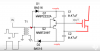
This thread would be just theoretical. For knowledge. This actually do not represent any circuit I build.
To switch Q2 On (For discharging something), you need to apply 20V (above 5V) to VGS. There are no Gate-Source resistors for simplification.
You need some kind of circuit which will have contain invertor with galvanic isolation to 20V or some kind of laser FV technology? And some RF/photo circuit for switching output state from primary side (flip-flop on secondary).
And let say it will be switching at hundreds of Mhz. There should be proper calculated gate-source resistors for specific frequency.
So how you will do it?
 
switching at hundreds of Mhz
100s of mhz? maybe? What are you building a RF transmitter?
Of the circuits I posted. I have used 2 and 3 some. Mostly I used the last one. (with the transistor added for faster turn off)
I have used these from 30khz to 200khz. Just a word of warning. They will not work at very low or very high duty cycle. With ease they will do 25% to 75%. Beyond that it get hard. They all can be 0% but not 100%.
120389
120391
120392

120393

Because you are using 50V MOSFETs the transformer isolation is not a problem. Most transformers I know of for this job are built to 2500V and 100khz. It will be easy to make one for low voltage and high frequency.
 
Almost all companies that make transformers have a gate drive transformers. Coil craft has 13 different types.

Here is a video from TI.com. I have used this the two transistor type for 30 years.
Here it is:
120401
 

Attachments

  • 1567869740370.png
    1567869740370.png
    59.3 KB · Views: 206
Last edited:
You should do the math. In input capacitance of the MOSFET and the frequency of 100mhz and 0 to 10V turn on voltage. It take much power just to turn on/off the MOSFET.
How much? Just for example?
 
It takes 50nS for the MOSFET to start to turn off from when you remove the Gate voltage.
There is 14nS of turn on delay.
It takes 65nS and 100nS for the current to rise and fall. turn on turn off time.
There is more or less 200nS of time. 100mhz=10nS. Even at 5mhz you could only get the part on and off with out moving any power.
You need to think 100khz.
Thanks fo timing. In was curious about power losses when switching mosfet on off. Bipolar transistors do better job?
 
curious about power losses when switching mosfet on off. Bipolar transistors do better job?
No. They do a different job. (different way)
Probably the MOSFET is better for 100A 50V but there are transistors that can do that. Because MOSFETs are easy to understand I think you should stay there.
I know you want low power loss. Each on and each off have power losses. This why power supplies do not run in at 100MHz.
 
Last edited:
Status
Not open for further replies.

Latest threads

New Articles From Microcontroller Tips

Back
Top