Continue to Site

Welcome to our site!

Electro Tech is an online community (with over 170,000 members) who enjoy talking about and building electronic circuits, projects and gadgets. To participate you need to register. Registration is free. Click here to register now.

  • Welcome to our site! Electro Tech is an online community (with over 170,000 members) who enjoy talking about and building electronic circuits, projects and gadgets. To participate you need to register. Registration is free. Click here to register now.

How to Time delay/Phase delaying a TTL signal

Status
Not open for further replies.

pavjayt

Member
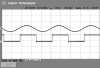
I have a source TTL which is derived from a sine wave (16KHz) at 0° phase. Using this TTL signal I am deriving a PLL. I would like to be able to add delay to this PLL so that I can adjust the rising edge of PLL output from 0° phase and +90° phase of sine wave (about 1/4 of its time period) from which its derived.

At present a 74HC4046 is my PLL IC.

Can someone suggest me how this can be done?

thanks
 

Attachments

  • IMG3.png
    IMG3.png
    10.6 KB · Views: 338
If we forget about PLL, how can I delay the TTL signal with user adjustable control between 0° phase and +90° phase of sine wave?
 
Two ways:

Analog- Use an op amp configured as a phase-shift (all-pass) circuit for the sine-wave such as this which will go for 0° to 180° (90° at one time-constant). If you need a lagging phase-shift instead of leading, simply reverse R (pot) and C. Note that the phase-shift changes with frequency.

Quasi Digital - Use a 555 as a one-shot to get the delay you need for the square-wave.
 
Is the sine wave frequency always 16kHz?
 
Since the wave period is ~60us you could use a simple R/C circuit and another gate to provide a delay up to ~15us.
 
I am trying to implement the delay using an op-amp and following the method in this article. Can someone try it in a simulation and let me know the R and C values that works best for a 16KHz sine wave with a delay adjustment of 0s to 15μs?

I tried using 10K pot with 0.001μF and it doesn't look good as the bottom of sine wave is flattening.

thanks
 
1. If you put a divider between the VCO output and the phase detector of the 4046 then you multiply the frequency up by whatever the divider value is. You then have discrete steps of phase that you can use. You just need a sync pulse once per 16kHz cycle to maintain a stable phase.

2. If you use an integrator as the filter between the phase comparator output (use the XOR version) and the input of the VCO the VCO will naturally be 90 degrees out of phase with the input. If you inject a DC current into the input of the integrator/filter you can shift the phase. If you go too far though it will tend to lose lock. Also integrators have a tendency to saturate which you would need to guard against. (1) is the better proposal.
 
Sorry to get off topic, but what is the actual GOAL of the final device? ie; 16kHz goes in, then it does what as the final goal?

It's just that we see lots of these threads asking about a specific issue, then it turns out later the whole job could have been done much better and easier, in some other way. :)
 
Its not exactly 16KHz, but it is pretty much stable upto one decimal point precision at a given value which will be always between 15KHz to 16KHz.

If you have access to the original sine wave you could use this simple phase shifter.

Use a variable pot to adjust the phase shift and select the correct phase to create the square wave.

E.
 

Attachments

  • AAesp02.gif
    AAesp02.gif
    53.9 KB · Views: 262
  • PhaseShift1.asc
    2 KB · Views: 157
1. If you put a divider between the VCO output and the phase detector of the 4046 then you multiply the frequency up by whatever the divider value is. You then have discrete steps of phase that you can use. You just need a sync pulse once per 16kHz cycle to maintain a stable phase.

Could you give me a schematic for this solution if you can? that would be really helpful.

I tried using a LM556 timer (as I have many of those ICs laying around) to induce delay, but the output is nothing. Below is my schematic. Any idea why its not working?

thanks
 
Last edited:
If you have access to the original sine wave you could use this simple phase shifter.

Use a variable pot to adjust the phase shift and select the correct phase to create the square wave.

E.

Thanks for your schematic Eric. I will try it right now.
 
Any idea why its not working?
Does your 'sig in' have a pull-up to V+ ?
 
If you have access to the original sine wave you could use this simple phase shifter.

Use a variable pot to adjust the phase shift and select the correct phase to create the square wave.

E.

Tried this and its working fine. The only think that I changed is to use 15V rather than 12V as I can see some distortion in the rising edge of the output at 12V. This can be used into my design, but I have access only to 5V on my digital board, are there any other variations of this using 5V or should it have to be above 12V?
 
Just curious. What keeps you from using the digital solution? Are you just trying to make a clock delayed from your signal?
 
Just curious. What keeps you from using the digital solution? Are you just trying to make a clock delayed from your signal?

Sorry Ron, I completed missed your reply. You know how gmail stacks emails from same id, I ended up seeing the recent post which is after yours. Your suggestion also looks pretty simple if using digital signal, I will definitely try it out on Monday.

thanks
 
Status
Not open for further replies.

Latest threads

Back
Top