Hello,
I'll explain things just by "common sens" first, then give you a sort of a little procedure to follow (to crawl and learn how to walk, you'll do it without thinking about it after a while) .. This seems long, but when done on paper, it takes 5 minutes.
D1P means Diode 1 Passing (or Conducting) .. D1B means D1 Blocked .. (So D2P means Diode 2 Passing and D2B means Diode 2 is blocked
")
of course )
All right,
You have Two diodes so you have four cases which are:
Case 1: D1P AND D2P
Case 2: D1P AND D2B
Case 3: D1B AND D2B
Case 4: D1B AND D2P
Does this make sens ? Logical, right ?
You may find that some of these cases are impossible (Once you'll get used to it, just by looking at it.. And you get used to it by writing things down and demonstrating stuff (as will be shown later) you will find an "absurd" result when following each diode's conduction condition (that we will see later) finding a result like (V1<50volts AND V1>100volts) for example, which is impossible.. )
Are you following me this far ? Does this make sens to you to this point ?
You are asked to draw V0 on ONE or MORE PERIODS.
You will find that Each case (of the four cases we found) is VERIFIED for a CERTAIN time interval and NOT VERIFIED for the REST of the time (Period T). Makes sens ?
So, imagine the time axis .. Each case will take a small piec of that axis (from 0 to T).. And for each intervalle V0 will take a certain allure/shape that might or might not be the same of the precedent. You'll travel your time/angle interval and draw V0 for each one.
Quick example of V0 shape in Circuit 2, suppose D2 is blocked from T1 to T2 .. Then V0 = V2 no matter the condition of Diode 1 (Because D2 is "kind of a bridge" if you look carefully.. If the bridge is broken, then no matter what happens on the other side, it doesn't matter on V0) .. So from T1 to T2, V0 will be the same as V2. (Of course, in this example, we didn't take into account ALL the conditions)
So, here goes the procedure to see things a little bit clearly (The explication of something is always more complex than the actual thing .. An explanation will never be simpler than the thing it's supposed to explain ..)
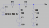
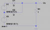
First, let's take Circuit 2 so we both talk about the same hting..
Imagine that every resistor is a simple wire. You can actually redraw your schematics replacing each resistor with a simple wire. (Suppose there is no tension drop)
Once you do that, draw apparent "points" (stress on the pen to draw a beautiful junction point, round) on the anode and cathode of each diode and write A on each anode and K on each cathode, with the adequate number, so A1 is the Diode1 Anode, K1 is the Diode1 Cathode, etc..
All this, just so you could "see" it clearly.. It's nothing woo hoo or vodoo.. Just to see things a bit clearer and on which potential is each electrode.
Then you write your conditions:
Diode 1 Passing/conducting (D1P) ==> VA1K1 >= Vs1 (Vs1 is the threshold tension. Depending on your "exercise", Vs is either supposed to be 0volt or you take into account Vs=0.7volt or Vs=0.6volt, etc ).
Diode 2 Passing (D2P)==> VA2K2 >= Vs2 (They might have the same value or not, I'm giving the "general case", you adapt it to your problem).
So, D1P ==> VA1 - VK1 >= Vs1 (Let's suppose Vs1=0v for simplicity) .. D1P ==> VA1 - VK1 >= 0 , then D1P ==> VA1 >= VK1
Diode 1 Passing ==> The tension in point A1 superior or equal to tension in point K1 .. Duh, right ? I'm writing this to others who may not find it "that" duh too..
D1P ==> VA1 >= VK1 (Passing)
D1B ==> VA1 < VK1 (Blocked)
In the same way:
D2P ==> VA2 >= VK2
D2B ==> VA2 < VK2
These are the Conduction Conditions of these diodes.
Let's look at circuit 2:
A1 is on V1
K1 is on V3
A2 is on V1
K2 is on V2
D1P ==> VA1 >= VK1 in other words D1P ==> V1 >= V3
D2P ==> VA2 >= VK2 in other words D2P ==> V1 >= V2
Does this make sens ? We're following each statement to the "actual condition" that makes each diode conduct or not.
You find "from when to when" this condition is true.
In other words, take the statement "D1 Passing" D1P ==> V1 >= V3 .. V1(t) = V1max*Sin(w1t+phi1)
V2(t) = V2max*Sin(w2t+phi2)
V3(t) = V3max*Sin(w3t+phi3)
When working with diodes or thyristors, it's better to work in angles than time . Theta = omega times t {omega being the pulsation}
You'll generally find two angles, one at which the diode starts conducting, the other at which the diode stops conducting/becomes blocked. These angles have the same "sinus" and the diode is passing/conducting between the two angles. (Draw the geometrical circle with Sinus, Cosinus and draw an arbitraty angle between 0 and Pi/4, then parachute it symetrically to the Sin axis on the other side of the circle. The arc between the two angles is the arc of conduction of the diode (in other words, the time intervalle of the diode conduction.. A period is 0 to T <==> 0 to 2*pi)
Theta1 and Theta2 depending on V1max, V2max, the pulsations and phase of each .. Replace V1 and V3 with their expressions and solve to find these angles (hence, the times at which each diode starts and stops conducting), so you could later draw V0 during a period}
WHEN you finish doing that.. You'll find things like
Case 1: Possible from Theta1 to Theta2 and V0 in this case is ...
Case 2: Possible from ........................................................
etc..
You will cover the WHOLE intervalle, and get the SHAPE of V0 (Output tension)...
If you have any question regarding any point, feel free to ask.

")