Continue to Site

Welcome to our site!

Electro Tech is an online community (with over 170,000 members) who enjoy talking about and building electronic circuits, projects and gadgets. To participate you need to register. Registration is free. Click here to register now.

  • Welcome to our site! Electro Tech is an online community (with over 170,000 members) who enjoy talking about and building electronic circuits, projects and gadgets. To participate you need to register. Registration is free. Click here to register now.

How to set up my 220V to 9Vx2 transformer?(What is wrong?)

Status
Not open for further replies.

sr13579

Member
So I tried to make an adaptor that can give me voltage around 9-10 Volts. There are total 5 wires as you can see in the attached image.
I am using a 1000 uF(25V) capacitor parallely after the bridge diodes as said. But the capacitor is heating up and I think the lid/head of the capacitor is pumped a little. Also the voltage is decreasing from 9V to 5.6 V. What have I done wrong? Should I change anything? Or what? Is my connection wrong? If there is a better way to connect what is it?(I am using the ground (yellow) and a blue wire to get 9V output. The seller said that using two blue wires would give me 18 V. I checked it with my Voltmeter)
 

Attachments

  • electro up transformer.jpg
    electro up transformer.jpg
    296.4 KB · Views: 377
Have you got your capacitor the right way round?

The voltage will be well over 10 V with a 9V transformer. The no-load voltage will be around 1.4 times or more times the nominal ac voltage, so to get around 14 - 15 V you should either connect between the yellow and blue wires. Alternatively you can connect the ac inputs of the bridge to the blue wires, and connect the capacitor between the +ve of the rectifier and the yellow wire.

You capacitor is probably damaged. The capacitor value depends on the maximum current, not on the voltage, so you haven't given us enough informations to work out the value.
 
What do you mean by that? Do I have to maintain the polarity as well?
Yes.
A 1000 μF 25 V capacitor will invariably be an electrolytic, unless it is huge and expensive. Electrolytic capacitors are polarised, and will generally be destroyed if run in reverse. The bulge an heat are signs on impending failure, usually caused by reversing them or by running them at too high a voltage or too hot, or just for too long.

There is almost always a mark on electrolytic capacitors to show the polarity.
 
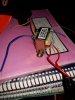
i got 2x of the transformers similar to what you have in hand only with single secondary winding
baically at the worst case situation ::
  1. the core material quality or the overall design is not (yet proven to be /!\) dangerous but it is below average e.g. :
  2. the efficiency is about 5 to 15%
  3. they heat up losing more power to increasing coils resistance
  4. from ohms law E=ir+U=i(r+R)=u+iR the useful power at R is maximum** at r=R e.g. u=U as E=u+U
    E=2U in this case** -- the output power would be half the total or the same dissipated at r (at inside the supply) also the voltage would be 4.5V for E=9V
  5. this is not idealized power source but a transformer
    a transformer in turn has a property to output more power to the lower load resistance - in other words
    the more power you drain from transformer the more power it outputs . . . up to a critical point - yet in another words
    IF in a case of ohmic power source the max output power is occurring at r=R THEN with a transformer the lesser the R the less becomes and r . . .
    . . . what i have experienced is the peak *** power output for 9V transformer is somewhere (very approximately) below 4V *** (did this test quite long ago)
your option is to use series 18V output (or if it's 2x4.5V a voltage doubler ) -- the most efficient is however a full wave rectifier - a 4 diode bridge
the practical output for my transformers 9V 300mA was some 50mA at 6V up to 300mA at near/below 4V *** (e.g. the particular chinese TF labels has the max possible values for either AC voltage or AC current but not simultaneously)

the nokia cell phone transformers 3.7V out (newer models) have efficiency around 50% (the best i've seen so far)

also the best (?a magical?) voltage transfer ratio for a line transformer (in a means of efficiency) is according to my statistics about 10 to 12
e.g. (that is) for 240V input it's 20 to 24V output with full wave rectified it is multiplied by that
1.4 times
max. 28 to 34V direct current output

so if you can configure 18V output it is l-i-k-e-l-y the best setup for your TF

-----------------

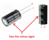
the electrolythic capacitors likely tolerate some excess to nominal - this is what i think - i never seen capacitor heating up at dc circuit or as a filter cap to rectifier bridge (as they are temperature rated 85°/105° C you don't want to spend any extra time at soldering them)

i have seen a rectifier bridges that have a reverse leakage/conductance/breakdown before the rated max.revese voltage -- because of that i always use 1N4007 for self built bridges , when required in series parallel or both with near matched alternate conductance shoulders for rectifiers
 
Last edited:
Here are photos of a 1000uF/25V capacitor with a minus label on one side and the minus wire beside the label and the positive wire on the other side.
It will be destroyed if it is connected with backwards polarity.
 

Attachments

  • 1000uF at 25V.png
    1000uF at 25V.png
    58.9 KB · Views: 284
Status
Not open for further replies.

Latest threads

New Articles From Microcontroller Tips

Back
Top