Continue to Site

Welcome to our site!

Electro Tech is an online community (with over 170,000 members) who enjoy talking about and building electronic circuits, projects and gadgets. To participate you need to register. Registration is free. Click here to register now.

  • Welcome to our site! Electro Tech is an online community (with over 170,000 members) who enjoy talking about and building electronic circuits, projects and gadgets. To participate you need to register. Registration is free. Click here to register now.

How to reduce the input current in Class-E DC-DC converters

Status
Not open for further replies.
Thanks Ron, I overlooked the little cap in mady's schema.
I guess if L1 is not saturating and Transformer has sufficient L and secondary has high coupling factor and secondary windings are balanced then the magnetics are ok.

Primary voltage sag seemed a bit high during output pulse.
vpri-vsec-png.93413
 
You mean that C1 = 68p and L1 = 17u. I have changed those values but the efficiency is too low.

I have designed by following the IEEE papers.
Hmm, I did find your FET.
Try these values. It checks out in the mid 90's for me.
 

Attachments

  • class e.png
    class e.png
    102.2 KB · Views: 303
Holy cow. :woot: Turn your back on a once a day thread and look what happens. I guess it goes to show you that you should refresh often. :oops:
 
RonV,
I placed a 82pF (or 100pf) cap across the MOSFET. That should help AC losses in the MOSFET.
That gets the voltage down to 300 volts. (which is too high!) The voltage rise time was too fast.
 

Attachments

  • class e RonS.asc
    3.1 KB · Views: 283
What is the plan to regulate? Change frequency to regulate how much current is output?
 
RonV,

The reason I know this circuit well is that it is very much like the horizontal section in a CRT monitor.
L1 is the flyback transformer. (could have higher inductance)
L6 is the H. yoke.
C1 is the "S" cap.
C4 + (cap of M1) is the flyback cap. (causes the half sign wave)
M1 is the H. switch and damper diode.
The zero voltage switching is caused by C4.
L6, C1 should be run close to resonant (in a CRT monitor it in not at resonant but near)
The transformer is where the lin-coil goes. In this case it steels away current from the LC resonant circuit.
The current ramps are much like a CRT monitor.
upload_2015-7-29_21-42-13.png
 
Hello ronsimpson,

Which type of core transformer have you been used?

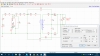
I have used the 4F1 core of the transformer. Now, I have changed to 3Mhz switching frequency of my circuit. I have tuned the C8 in the circuit in order to get the soft switching (ZVS). But, still the efficiency is 76% only. Here, I have used the two different types of the MOSFET's (i.e: EPC2025 and IPZ65R019C7) and see the results how it be.

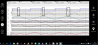
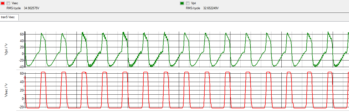
When the circuit running with the EPC2025 MOSFET, Even the circuit satisfying the ZVS (zero-voltage switching) condition, the circuit efficiency is 76%.
So, how to improve the efficiency with this MOSFET?

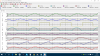
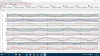
When the circuit running with the IPZ65R019C7 MOSFET, the circuit not satisfying the ZVS (zero-voltage switching) condition (see in the waveforms), I have tune the component values as following the below mentioned document. But, the circuit efficiency is 76%.
https://www.cs.berkeley.edu/~culler/AIIT/papers/radio/Sokal AACD5-poweramps.pdf
So, how to satisfy the ZVS condition with this MOSFET?

(OR)

Is there any problem with the core parameters of the materials like:
Effective magnetic length ‘le’, Effective permeability of the core ‘μe’ and Area of cross section ‘Ae’.
If you think there is problem with those materials, how to calculate them? What are the parameters we need to consider while calculating them?

Please, Can you tell me that where is the problem in the circuit and how to improve the efficiency of the circuit?
 

Attachments

  • Class-E Converter Circuit With EPC2025 MOSFET.png
    Class-E Converter Circuit With EPC2025 MOSFET.png
    34.6 KB · Views: 332
  • Class-E Converter Waveforms with EPC2025 MOSFET.png
    Class-E Converter Waveforms with EPC2025 MOSFET.png
    34 KB · Views: 323
  • Class-E Converter Circuit With IPZ65R019C7 MOSFET.png
    Class-E Converter Circuit With IPZ65R019C7 MOSFET.png
    33.1 KB · Views: 310
  • Class-E Converter Waveforms with IPZ65R019C7 MOSFET.png
    Class-E Converter Waveforms with IPZ65R019C7 MOSFET.png
    155 KB · Views: 306
Last edited:
I am working on Class-E DC-DC converter circuit. My input 60V, output 15V and switching frequency is 3MHz. But, In my circuit when I am giving the input voltage as 60V which is not getting at the primary side of the transformer. So, which values I have to tune. Please, can you see my circuit and could help me?
 

Attachments

  • Circuit with 3MHz Switching Frequency.png
    Circuit with 3MHz Switching Frequency.png
    17.1 KB · Views: 307
  • Circuit with 3MHz Switching Frequency Waveforms.png
    Circuit with 3MHz Switching Frequency Waveforms.png
    41.1 KB · Views: 303
What are the transformer parameters? Neither they nor the V2 parameters are shown.
 
Knowing the turns ratio what is the primary load with secondary at 14 Ω

Is this steady state?

How does it look with no load , 50% load?
 
Last edited:
Hello Tony,

Please, Ignore the First Thread

The both ideal and practical transformer runs in the SIMetrix simulation tool.

The above I have mentioned circuit with the Ideal transformer and its waveforms. Leave it the above circuit, anyhow we are not used in the real-time (hardware designing).

Here, I have attaching the practical transformer circuit and its simulation waveforms. But, I am using the Planner 4F1 transformer which is already exits. If we want to change any changes in order to get the soft-switching we have to change only in the other than the transformer.

My circuit has to get the soft- switching in both cases like Full-load (12 ohms) and Light-load (42 ohms). So, how we can do that? What are the components we have to tune? and Is there any processor to do that?
 

Attachments

  • The circuit with practical transformer.png
    The circuit with practical transformer.png
    64.3 KB · Views: 308
  • with full load.png
    with full load.png
    71.9 KB · Views: 282
  • with light load.png
    with light load.png
    71.5 KB · Views: 290
Last edited:
Where did you get this circuit? Is the EPC2012 supposed to be shorting out the 60V power supply when a voltage is applied to the gate? Seems a bit fishy to me. Then again, I've never designed a DC-DC converter.
 
Where did you get this circuit? Is the EPC2012 supposed to be shorting out the 60V power supply when a voltage is applied to the gate? Seems a bit fishy to me. Then again, I've never designed a DC-DC converter.

Below, I have given the circuit and waveforms whatever I am using. Please, Ignore the first thread.
 
Below, I have given the circuit and waveforms whatever I am using. Please, Ignore the first thread.

That doesn't answer my question.

Where did you get the circuit? Did you design it yourself? If so, what references did you use?
 
What are all your design specifications for the power supply and transformer?
 
What are all your design specifications for the power supply and transformer?

The specifications are:
Vin-60V, Vout-15V, Pout-16W, Fswi-3MHz, 4:1 tuns transformer ratio, transformer coupling factor 0.97, transformer primary inductance 4.88uH, core meterial 4F1,
Ae -43.4858, Le-25.8 and Ue-36.

Here, I have attached documents which have followed from the IEEE paper (see the example in page number 129). Only, the chock inductor calculated from the another document which is mentioned the name as a chock calculations.
 

Attachments

  • Designed values.pdf
    1.1 MB · Views: 341
  • Chock calculations.pdf
    450.4 KB · Views: 284
  • Chock calculations1.pdf
    519 KB · Views: 274
I am using the TPH3002 and TPH3006 MOSFET's in my circuit. When I am going to run the circuit in the simulations. It's showing these error messages.
So, please could you help me....

Error messages:
There are errors in the circuit. Simulation aborted
TPH3002.txt (74): lint2 29 28 0.20nH rser=0.12
*** ERROR *** Unknown parameter 'rser'

TPH3002.txt (75): lint3 29 13 0.33nH rser=0.01
*** ERROR *** Unknown parameter 'rser'

There are errors in the circuit. Simulation aborted
TPH3006.txt (78): lint2 29 28 0.20nH rser=0.12
*** ERROR *** Unknown parameter 'rser'

TPH3006.txt (79): lint3 29 13 0.33nH rser=0.01
*** ERROR *** Unknown parameter 'rser'
 

Attachments

  • TPH3002.txt
    1.8 KB · Views: 312
  • TPH3006.txt
    1.9 KB · Views: 352
  • Schematic.png
    Schematic.png
    24.3 KB · Views: 294
Status
Not open for further replies.

Latest threads

Back
Top