The specifications of the circuit is Vin=60V, Fsw=5Mhz, Vout=15V, Pout=16W. I am getting the Vout is 18V, Iout is 1.2A and Iin is 0.980A. So, If I reduce the input current I will get the high efficiency of the circuit. So, please suggest me what I suppose to do in order to reduce the input current of the circuit.
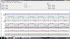
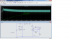
Here, I have attached the circuit schematic and waveforms.
Here, I have attached the circuit schematic and waveforms.