I need to design a circuit that will take two inputs (from pots), both of which have a range from 0V to +5V.
From these two inputs, I then need to output the one which has the highest value.
e.g.
Input 1 = +2V
Input 2 = +4V
Therefore output = +4V
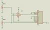
Does anyone know of a circuit that can do this ?
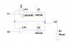
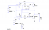
I thought of using 2 diodes (as an analogue OR gate) but then I would get a voltage drop accross the diodes.
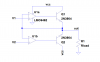
There must be some way of doing it using op-amps and resistors etc ?
From these two inputs, I then need to output the one which has the highest value.
e.g.
Input 1 = +2V
Input 2 = +4V
Therefore output = +4V
Does anyone know of a circuit that can do this ?
I thought of using 2 diodes (as an analogue OR gate) but then I would get a voltage drop accross the diodes.
There must be some way of doing it using op-amps and resistors etc ?