Electro Tech is an online community (with over 170,000 members) who enjoy talking about and building electronic circuits, projects and gadgets. To participate you need to register. Registration is free. Click here to register now.
Welcome to our site! Electro Tech is an online community (with over 170,000 members) who enjoy talking about and building electronic circuits, projects and gadgets. To participate you need to register. Registration is free. Click here to register now.
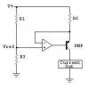
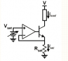
I am stuck with this project here. I was trying to make a voltage controlled current source which can generate 1A with 5V. I used a digaram of 741. But it didn't work. Is there anyone who can help me with showing me a circuit that can work? Thanks.
That is like telling a mechanic that your car does noqt work, but nothing about symptoms, make, model, ect. A schematic isnt everything, its pretty much the only thing.
dknguyen has already provided a shematic. The only aditional to fill in is voltage source and pin numbers, and you're good to go.
And of course the resistor values.
The design of a 741 opamp is 50 (!) years old and it was designed to use ONLY a plus and minus (total of 30V) supply.
Its useable input voltage range is limited and its output voltage swing is also not much. It has the same low maximum output current of most opamps.
A newer opamp can use a single supply voltage that is much lower and would work much better.
Note that the 741 will only work to within about 2V of the negative rail, so if you have a single positive supply voltage, the minimum input voltage will be 2V.
A single-supply op amp, such as an LM324, or any rail-rail op amp will go down to zero volts on the input.
dknguyen has already provided a shematic. The only aditional to fill in is voltage source and pin numbers, and you're good to go.
And of course the resistor values.
This is a very condescending and pedantic answer to the people who are attempting to help you.
We know that there are hundreds of circuits on the web. I would easily bet that 2/3 of them have fatal flaws. Additionally, you may have substituted components, or changed values, or exceeded ratings. Audioguru's comment that a 741 won't work with a 5 volt supply is a prime example of the latter.
Without a schematic and even actual images of what you built, how can you reasonably expect to obtain help?
This site uses cookies to help personalise content, tailor your experience and to keep you logged in if you register.
By continuing to use this site, you are consenting to our use of cookies.

")