Electro Tech is an online community (with over 170,000 members) who enjoy talking about and building electronic circuits, projects and gadgets. To participate you need to register. Registration is free. Click here to register now.
Welcome to our site! Electro Tech is an online community (with over 170,000 members) who enjoy talking about and building electronic circuits, projects and gadgets. To participate you need to register. Registration is free. Click here to register now.
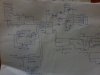
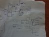
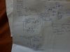
I Can't imagine any Manufacture supplying a Poor Quality, HAND DRAWN Circuit like that.
And without knowing the Programming for the "PIC", It isn't a Practical circuit to Determine what it is ment to do or to Duplicate it .
I Can't imagine any Manufacture supplying a Poor Quality, HAND DRAWN Circuit like that.
And without knowing the Programming for the "PIC", It isn't a Practical circuit to Determine what it is ment to do or to Duplicate it
This site uses cookies to help personalise content, tailor your experience and to keep you logged in if you register.
By continuing to use this site, you are consenting to our use of cookies.