Continue to Site

Welcome to our site!

Electro Tech is an online community (with over 170,000 members) who enjoy talking about and building electronic circuits, projects and gadgets. To participate you need to register. Registration is free. Click here to register now.

  • Welcome to our site! Electro Tech is an online community (with over 170,000 members) who enjoy talking about and building electronic circuits, projects and gadgets. To participate you need to register. Registration is free. Click here to register now.

How to generate a Modified sin wave...?

Status
Not open for further replies.

koolguy

Active Member
Hi,

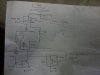
Recently I am working on Inverter. After using a SG3524 PWM chip for square wave with output 220V regulation on load.
now i want to go for modified sin wave as the current drawn on square wave is also high than modified sin wave and some appliance does not work well.

Audio guru has posted a M. sin wave ckt in my previous thread using 4047 and 4001 which is working but there is no feed back option in it...
so, kindly help me if u have any idea related

sorry i can't upload image don't know why??
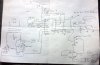
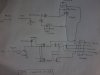
i have seen this but how to generate it!!
**broken link removed**
 
Last edited:
Hi,

The SG chip has built in regulation circuitry. All you have to do is provide some feedback possibly filtered. If the feedback constant is right it will regulate at around 120vac (assuming that's what you want) and you will obtain your modified sine because that SG chip will automatically cut back the pattern to a shorter pulse to get the right voltage output.
To start with, you'd want to full wave rectify the output so you can get a Dc feedback voltage. It will be pulsing so you have to do a little filtering too.
Once you proved the SG chip with feedback it will cut back as required, the theoretical duty cycle is 83 percent but it may vary a little with load.

The typical patterns are about 80 percent duty cycle for each half cycle, and about 145v pulse height. That's typical on the modern modified sine inverters.

Of course you have to provide phase switching to switch the output from a positive pulse to a negative pulse, but that's just keeping track of every other SG pulse and steering it to turn on the right set of transistors.
 
Last edited:
hi,

The SG chip has built in regulation circuitry. All you have to do is provide some feedback possibly filtered. If the feedback constant is right it will regulate at around 120vac (assuming that's what you want) and you will obtain your modified sine because that SG chip will automatically cut back the pattern to a shorter pulse to get the right voltage output.


The voltage regulation is working i have connected output then converted in dc then used a voltage dived to have 14V Dc max to 2.5V at no-load..
anyway i have to go with micro controller to generate stable modified sine wave with PWM in it!!
 
Hi,

yes that's probably the best way to do this. That way you can get any pattern you want.

Can also use a 555 and flip flop.
 
Last edited:
yes that's probably the best way to do this. That way you can get any pattern you want.

Can also use a 555 and flip flop.

Hi again,

I already told i want to go with pic micro controller b'coz its stable and latest then other chips with modified sine wave as in SG 3524 can't do this..!!
 
Hi again,


Oh ok well it sounds like you already have this pretty well planned out then. So let us know how it all works once you get it up and running ok? Some pics would be nice to see too, and waveforms if you can get them. I'd like to see the output pattern. I did a simulation not too long ago just so i could test some other things that would be (in real life) plugged into it. We could compare notes.
 
Last edited:
This is the output of Sg3524 in CRO ....
so, can u help me know with uC or any other to have at least modified sine wave..?..??
 

Attachments

  • 2012-12-10 11.56.48.jpg
    2012-12-10 11.56.48.jpg
    127.7 KB · Views: 324
Hi again,

Oh ok yes that looks typical, thanks for posting that pic.

With a micro controller chip all you have to do is program a delay into the chip for when it is to provide a turn on for one set of transistors, then another delay and output for the other set of transistors (assuming a full H bridge which is typical). To get voltage regulation however you have to provide feedback from the output, which would be filtered one way or another, then used to adjust the output for the correct amplitude. Without voltage regulation you only have to program delays and use two outputs, so maybe you can start with that first and see how it goes. There's a little bit too this kind of project so it isnt a bad idea to start with no regulation and add that later. Alternately you could provide feed forward regulation, where you measure the input voltage and knowing the approximate response of the output to said supply voltage you can adjust the output pulse width to compensate for the drop when the input voltage droops for example. If you intend to run on a 12v battery then the droop might go as low as 11v or so, but you may want to allow inputs of up to 15v to use on a car that is running, so the input range would be about 11 to 15v.
It would be a good exercise for you to calculate the required output pulse width as the input changes from 11 to 15v :)
 
Last edited:
ok, for feedback some people use opt-coupler like 4n35 will that make some difference then voltage divider network consisting of R??
 
here is the schematic...
1 contain only sg3524 circuit
2. contain the mosfet driver ckt only...
if i want to go with IGBT then changes i have to do??
 

Attachments

  • 2012-12-10 09.21.12.jpg
    2012-12-10 09.21.12.jpg
    399 KB · Views: 321
  • 5-Ritesh.JPG
    5-Ritesh.JPG
    121.5 KB · Views: 1,667
Hello again,


You have to look up the differences in driving a MOSFET as compared to driving an IGBT.

Opto couplers are sometimes used, but it's best to use them at low current drive to preserve the internal LED which ages. You only need an opto if the output has to be isolated and is already isolated from the mains supply via a dual winding transformer.
 
OK, if we talk about ferrite core transformer working how we choose them is there any difference in there rating,etc etc?
 
Hi,

Well you do have to look up their ratings, max current, max drive voltage, etc. You have to download the data sheets for the parts and decide which is better and cost effective. That's a part of every design really. Of course you should allow some margin of safety so that the parts are not stressed too hard. 150v parts in an 100v application might be good, unless the voltage can go twice as high as the source voltage and then you need a rating greater than 200v for example. If there are any spikes even after snubbing you also have to account for that.
 
Hi

I have this schematic of UPS for change over supply......
but i can't understand use of Diac and Triac here??
 

Attachments

  • 2012-12-24 23.37.02.jpg
    2012-12-24 23.37.02.jpg
    342.5 KB · Views: 295
but i can't understand use of Diac and Triac here??
Its an adjustable power, solid state, AC swicth. Like a dimmer.
 
Last edited:
Status
Not open for further replies.

Latest threads

Back
Top