Fluffyboii
Active Member
Hi,
I have this problem for a long time now. Whenever I power something from USB that has analog circuitry inside, high pitched annoying random noise invades the circuit. I was able to eliminate some of it by using a BJT capacitance multiplier but some high pitched random stuff still appears on the output. I learned that this is most likely from ground loop issue and there are some devices that can be bought that are especially build to eliminate this issue. Only problem is that these devices are usually expensive and hard to find.
It is also said that this issue can be eliminated by having the circuit galvanic isolated.
For example DiyPerks electret mic circuit runs from USB power. But his diy microphone has no annoying noises at the end. Only logical reason can be that the NMA0515 isolated boost converter is eliminating it. Finding this device locally is a nightmare though. I can only buy it from china and unknown sources. He also has 4400uF capacitance connected directly to USB power. Wouldn't this cause sparks at the USB port when you plug it in and ruin it overtime.

Regular non isolated boost converters are cheap but they don't fix the issue. For example this is the one I got which directly converts 5V USB up to 26V. I soldered two pole low pass capacitance multiplier with 2000uF and 2.6K resistors (3.3K parallel with 12K because 12K was too much and caps were taking too long to charge) which doesn't really help. Seems like generally adding low pass filters to the circuit that will be powered doesn't really work to fight against this noise.

I have multiple transformer cores so I can wind a transformer for making a galvanic isolated boost converter. Any simple topologies for making a boost converter that will eliminate USB noise? Most of the galvanic isolated DC-DC boost circuits are too complex for my liking. If it can go up to 48V it would be nice to make a USB powered Phantom Power supply. But a lower voltage like 25V would work as well. My objective is making a low noise USB power supply that I can use for my future USB powered projects.
For lowest noise possible I found out that using a simple transformer to lower mains voltage, full bridge rectify it and use something like 7809 regulator with lots of filtering works really well. But I don't really want to make it work from mains and I need higher voltage.
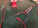
I also found out that when using 2 pin electret capsules with build in JFETs and powering the preamplifier circuit from batteries and shielding the circuit with metal case some noise still appears when gain is increased. This noise doesn't change with changing the op amp from generic TL081 to something else. Which only leaves the JFET itself as the only possible noise source. The capsule I tested was this head part from some random microphone I found for cheap:

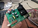
audiogrus pinned electret preamp circuit. All metal resistors, additional two pole input low pass with 10ohm resistor and 100uF capacitors, decoupling caps + one directly at the op amp inputs. As I said I put it inside a metal contained and grounded both the electret capsule shield and the container itself. Still did not get low noise signal out of it.

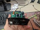
rjenkinsgb made this simple amplifier that can run off the mic line voltage and it performs much better with a cheap two pin small capsule. It basically has no noise compared with the one on top at similar output levels. I am not sure how can it works so well with just one active element.
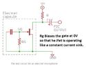
I also just purchased a 34mm bare electret capsule accidentally thinking it was a true condenser one (they look very similar). Default configuration on sale page is this:

Can I configure it as a 3 terminal electret instead (is this technically 3 terminal). From my understanding and testing in real life when I have some negative feedback at the internal JFET (degeneration resistor) the gain of the capsule decreases but SNR ratio increases. Then I can amplify it with a regular Op Amp and have much better Gain/Noise ratio since Op Amp performs better than a single JFET amplifying most of the signal. Looks like the picture at the bottom is how people usually wire bare electret capsules. JFET directly connected to the capsule. He then connects it to the circuit at the first image having resistors both at the drain and source.

I also want to add that I wanted to use this capsule with rjenkinsgb's microphone upgrade circuit. He took the trouble of sending one to me and I really appreciate it. I am sure it works really well but the fact that I accidentally bought an electret capsule and me having no XLR USB interface with Phantom supply makes it complicated.
Can I leave the red circled area unoccupied on the PCB and directly connect the middle positive plate of the bare electret to Gate of Q4 JFET and ground its negative plate to circuit's ground.

Sorry for posting so many different thing in one topic. I just can't get this out of my head.
I have this problem for a long time now. Whenever I power something from USB that has analog circuitry inside, high pitched annoying random noise invades the circuit. I was able to eliminate some of it by using a BJT capacitance multiplier but some high pitched random stuff still appears on the output. I learned that this is most likely from ground loop issue and there are some devices that can be bought that are especially build to eliminate this issue. Only problem is that these devices are usually expensive and hard to find.
It is also said that this issue can be eliminated by having the circuit galvanic isolated.
For example DiyPerks electret mic circuit runs from USB power. But his diy microphone has no annoying noises at the end. Only logical reason can be that the NMA0515 isolated boost converter is eliminating it. Finding this device locally is a nightmare though. I can only buy it from china and unknown sources. He also has 4400uF capacitance connected directly to USB power. Wouldn't this cause sparks at the USB port when you plug it in and ruin it overtime.
Regular non isolated boost converters are cheap but they don't fix the issue. For example this is the one I got which directly converts 5V USB up to 26V. I soldered two pole low pass capacitance multiplier with 2000uF and 2.6K resistors (3.3K parallel with 12K because 12K was too much and caps were taking too long to charge) which doesn't really help. Seems like generally adding low pass filters to the circuit that will be powered doesn't really work to fight against this noise.
I have multiple transformer cores so I can wind a transformer for making a galvanic isolated boost converter. Any simple topologies for making a boost converter that will eliminate USB noise? Most of the galvanic isolated DC-DC boost circuits are too complex for my liking. If it can go up to 48V it would be nice to make a USB powered Phantom Power supply. But a lower voltage like 25V would work as well. My objective is making a low noise USB power supply that I can use for my future USB powered projects.
For lowest noise possible I found out that using a simple transformer to lower mains voltage, full bridge rectify it and use something like 7809 regulator with lots of filtering works really well. But I don't really want to make it work from mains and I need higher voltage.
I also found out that when using 2 pin electret capsules with build in JFETs and powering the preamplifier circuit from batteries and shielding the circuit with metal case some noise still appears when gain is increased. This noise doesn't change with changing the op amp from generic TL081 to something else. Which only leaves the JFET itself as the only possible noise source. The capsule I tested was this head part from some random microphone I found for cheap:
audiogrus pinned electret preamp circuit. All metal resistors, additional two pole input low pass with 10ohm resistor and 100uF capacitors, decoupling caps + one directly at the op amp inputs. As I said I put it inside a metal contained and grounded both the electret capsule shield and the container itself. Still did not get low noise signal out of it.
rjenkinsgb made this simple amplifier that can run off the mic line voltage and it performs much better with a cheap two pin small capsule. It basically has no noise compared with the one on top at similar output levels. I am not sure how can it works so well with just one active element.
I also just purchased a 34mm bare electret capsule accidentally thinking it was a true condenser one (they look very similar). Default configuration on sale page is this:
Can I configure it as a 3 terminal electret instead (is this technically 3 terminal). From my understanding and testing in real life when I have some negative feedback at the internal JFET (degeneration resistor) the gain of the capsule decreases but SNR ratio increases. Then I can amplify it with a regular Op Amp and have much better Gain/Noise ratio since Op Amp performs better than a single JFET amplifying most of the signal. Looks like the picture at the bottom is how people usually wire bare electret capsules. JFET directly connected to the capsule. He then connects it to the circuit at the first image having resistors both at the drain and source.
I also want to add that I wanted to use this capsule with rjenkinsgb's microphone upgrade circuit. He took the trouble of sending one to me and I really appreciate it. I am sure it works really well but the fact that I accidentally bought an electret capsule and me having no XLR USB interface with Phantom supply makes it complicated.
Can I leave the red circled area unoccupied on the PCB and directly connect the middle positive plate of the bare electret to Gate of Q4 JFET and ground its negative plate to circuit's ground.
Sorry for posting so many different thing in one topic. I just can't get this out of my head.
Last edited: