Continue to Site

Welcome to our site!

Electro Tech is an online community (with over 170,000 members) who enjoy talking about and building electronic circuits, projects and gadgets. To participate you need to register. Registration is free. Click here to register now.

  • Welcome to our site! Electro Tech is an online community (with over 170,000 members) who enjoy talking about and building electronic circuits, projects and gadgets. To participate you need to register. Registration is free. Click here to register now.

how to design the window lifter motor continuously running forward and reverse with control of magnetic reed switch

Status
Not open for further replies.

arunpandiant24

New Member
Hi I am Arun,
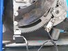
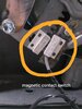
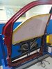
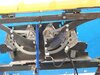
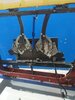
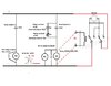
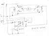
I'm doing this project to finding the window lifter motor capacity. here the motor doesn't run reversely without changing the polarity. I'm doing this circuit with the help of 12v relay, reed switch, magnet, transistor, resistor, capacitor. the reed switch placed in two fixed places for attracting the by magnet .the magnet placed at motor gear teeth. upper and lower reed switch attracted by the magnet accordingly motor will run at forward and reverse the condition.

Operating conditions :
1, motor move forward at a certain distance until the upper side reed switch attracted by the magnet. when the power supply switch on.
2, when reed switch attracted by the magnet remains the stop and start to reverse direction.
3, the motor move reverse at a certain distance until the lower side reed switch attracted by the magnet.
4.when reed switch attracted by the magnet remains the stop and start to forward direction.

I want this cycles continuously running. I hope better reply here from you
 

Attachments

  • reedswitch placement setup.jpeg
    reedswitch placement setup.jpeg
    93.7 KB · Views: 212
  • reedswitch.jpeg
    reedswitch.jpeg
    98.1 KB · Views: 317
  • whole setup.jpeg
    whole setup.jpeg
    105.6 KB · Views: 214
  • window lift down by the motor.jpeg
    window lift down by the motor.jpeg
    107 KB · Views: 227
  • window lift up by the motor.jpeg
    window lift up by the motor.jpeg
    85.1 KB · Views: 216
Do you want to pause at each reversal or just reverse the motor without allowing it to stop first ? (It is not good practice to reverse the motor without allowing it to stop.) What is the contact arrangement of your relay ? (SPST, SPDT, DPST, DPDT etc.)

Les.
 
First of all thanks for your feedback, I need to reverse the motor without allowing it to stop. because I try to design for the motor number of cycles performed to lift up and down its for a hours suppose if I am taking this process to a day I should add time delay circuit because prevention of motor heating. SRD-12VDC-SL-C type of relays used. but I tried to design and not getting good results.
I hope you supporting.
 
I'd like to know where your going to use this motor for what application I wonder? off the shelf motor doesn't do the job ? Unless you want to lift like laminated bulletproof glass. Nice project anyway
 
This looks similar to the classic chicken coop door controller, if you google it you'll find some examples.
If you dont want the complexity of pausing the motor at reversal then you could improve things by limiting the current with a power resistor in one of the supply lines.
 
You can't do what you want with single SPDT relay (Which is what you have from the relay datasheet.) unless you have a a split power supply. ( -12V 0V +12V)
Here is a way to do it using 3 x SPDT relays. (I may be able to work out how to do it with just two if I spend some more time thinking about it.
200420.jpg


The bottom left relay is triggered on by one limit switch and latches on via the diode from it's NO contact. In that condition it energises the top right relay driving the motor in one direction. When the other limit switch closes it shorts the base - emitter junction of the transistor causing it to stop conducting. This causes the bottom left relay to drop out. In this condition it's NC contact energises the top left relay driving the motor in the other direction. The diodes can be any of the 1N400x series. Your picture seems to show a normal car window motor. These will only be designed for intermittent use so they would overheat in your application very quickly.

Les.
 
What you need is to wire the circuit to latch and unlatch the relay via both read switch. at start relay is not energized (latched) so the motor moves to one direction and hit the limit and relay get energized (latched) then direction changes. it moves opposite direction until the next switch that unlatches the relay. it is similar to simple start stop motor starter.
1st switch should be wired via NO contact
2nd switch should be wired via NC contact
if you need i can post a schematic later.
 
This sounds like a life-cycle test or long-term reliability test. In that case, slamming the motor from forward to reverse is a feature, not a bug. One DPDT impulse relay (plus a suppression diode) can do the whole project with no other parts. Both switches are wired in parallel. When either one closes, the relay changes state, reversing the motor.

Note: If there is no transient suppression across the motor, add two 15 V zener diodes, back-to-back.

ak
 

Attachments

  • Impulse-S89RS90R_0505.pdf
    76.6 KB · Views: 207
If it's a life-cycle test for future fitment in a car, it's never going to be slammed from one direction to another, because the motors are controlled by a module, probably in the door, that will pause the motor momentarily before reversing it.

I would try to get an actual door module to run it.

Is it a lifter for armoured glass?
 
What you need is to wire the circuit to latch and unlatch the relay via both read switch. at start relay is not energized (latched) so the motor moves to one direction and hit the limit and relay get energized (latched) then direction changes. it moves opposite direction until the next switch that unlatches the relay. it is similar to simple start stop motor starter.
1st switch should be wired via NO contact
2nd switch should be wired via NC contact
if you need i can post a schematic later.


thanks for your feedback.

yes I need schematic, it could be nice.
 
If it's a life-cycle test for future fitment in a car, it's never going to be slammed from one direction to another, because the motors are controlled by a module, probably in the door, that will pause the motor momentarily before reversing it.

I would try to get an actual door module to run it.

Is it a lifter for armoured glass?

yeah it is armoured glass. it's for only life cycle test purpose, not fitment in a car.
 
thanks for your feedback.

yes I need schematic, it could be nice.

see attached schematic, since the read switch shown is only having 2 wires and normally open contacts, one of the switch operation is to be inverted by additional SPDT relay. Another SPDT relay is used parallel to DPDT. it can be replaced by a 3PDT relay.
 

Attachments

  • window motor schematic.jpg
    window motor schematic.jpg
    87.6 KB · Views: 209
This circuit should work for your motor direction control.

It uses a NE555 timer IC as an Set/Reset latch.
Closing S1 will make the output of the 555 go low, turning the relay off and causing the motor to go in one direction,
Closing S2 will make the output of the 555 go high, turning the relay on and causing the motor to change direction.

How it works:
When the voltage on the threshold pin of 555 goes above 2/3rds (8V) of the Vcc voltage, the 555 output goes low.
When the voltage on the trigger pin of 555 goes below 1/3rd (4V) of the Vcc voltage, the 555 output goes high.

In this circuit, they are tied together and held at 1/2 (6V) of Vcc. We'll call this point, input.
When S1 is closed, the input is pulled up to about 11 Volts, well above the threshold trip voltage.
When S2 is closed, the input is pulled down to about 1 volt, well below the trigger trip voltage.
The input is the green line in the timing diagram. The output in the red line.

Ignore V2 and V3. They are there to run the simulation.

555 S-R latch.jpg
 
You can't do what you want with single SPDT relay (Which is what you have from the relay datasheet.) unless you have a a split power supply. ( -12V 0V +12V)
Here is a way to do it using 3 x SPDT relays. (I may be able to work out how to do it with just two if I spend some more time thinking about it.
View attachment 124537


The bottom left relay is triggered on by one limit switch and latches on via the diode from it's NO contact. In that condition it energises the top right relay driving the motor in one direction. When the other limit switch closes it shorts the base - emitter junction of the transistor causing it to stop conducting. This causes the bottom left relay to drop out. In this condition it's NC contact energises the top left relay driving the motor in the other direction. The diodes can be any of the 1N400x series. Your picture seems to show a normal car window motor. These will only be designed for intermittent use so they would overheat in your application very quickly.

Les.


I accept your case. because the motor getting heat very quickly. that's why think to instal off delay timing circuit. it's for only demo purpose. 1) I need 1 minute (approximately) off delay for the forward condition. after 1 minute the motor get reverse. 2) 1 minute off delay for reverse condition. after 1 minute(approximately) the motor get forward. due to prevention of heating of the motor and this cycle will running continuously.

please give me some help
 

Attachments

  • 200420.jpg
    200420.jpg
    267.6 KB · Views: 187
You were told that window motors will overheat running them continuously. If you think about the normal way you would use them in a car then there would normally long periods between a single of a few cycles of operation. If I was doing this project I would probably use a small microcontroller such as a PIC12F1840 or an Atmel ATtiny13A. This would result in a very low component count. Can you use microcontrollers ? (Have the hardware to program them and the knowledge to write the code to run on them ?) Other solutions for the 1 minute delay would be an LM555 or a CD4060 Which type of solution suits your requirements ?

Les.
 
Actuators like this in cars are usually only used for short times, so there is little or no cooling needed for the motors. If over-used, they will burn out. It is therefore common to have "play-prevention" which stops the actuators being used a lot without breaks. That will be built into the control module that runs the window.

If you are wanting to test the motors thousands of times to see if they wear out, it's quite legitimate to add additional cooling so that the process can be speeded up.

If you are testing for correct operation at low temperatures in a temperature chamber, which you should, you should leave the motors some time to get to near the same temperature as the chamber before checking the operation.

I've worked on car actuators, and they are often very difficult to operate at low temperatures. I suspect that it mainly due to the grease on the gears getting stiff. The effect is non-linear. The drive current can double between -20 deg C and -30 deg C. Running an actuator motor with only short breaks will keep it and the gears well above the ambient temperature, so will make it look like the actuator performs fine at the low temperatures, when if left to cool down, it doesn't work at all well.
 
You were told that window motors will overheat running them continuously. If you think about the normal way you would use them in a car then there would normally long periods between a single of a few cycles of operation. If I was doing this project I would probably use a small microcontroller such as a PIC12F1840 or an Atmel ATtiny13A. This would result in a very low component count. Can you use microcontrollers ? (Have the hardware to program them and the knowledge to write the code to run on them ?) Other solutions for the 1 minute delay would be an LM555 or a CD4060 Which type of solution suits your requirements ?

Les.


I am doing this project for demo purpose only. can you please add off delay circuit and post for the same.
 
You need to answer the questions at the end of post #16 first. (The microcontroller solution is the easiest for me to design.) I am NOT going to spend the time working out the three solutions.

Les.
 
You were told that window motors will overheat running them continuously. If you think about the normal way you would use them in a car then there would normally long periods between a single of a few cycles of operation. If I was doing this project I would probably use a small microcontroller such as a PIC12F1840 or an Atmel ATtiny13A. This would result in a very low component count. Can you use microcontrollers ? (Have the hardware to program them and the knowledge to write the code to run on them ?) Other solutions for the 1 minute delay would be an LM555 or a CD4060 Which type of solution suits your requirements ?

Les.

I don't use microcontroller .this for only demo purpose. I need 1-minute delay with simple circuits of components . I hope you can help me out.
 
Status
Not open for further replies.

Latest threads

New Articles From Microcontroller Tips

Back
Top