Electro Tech is an online community (with over 170,000 members) who enjoy talking about and building electronic circuits, projects and gadgets. To participate you need to register. Registration is free. Click here to register now.
Welcome to our site! Electro Tech is an online community (with over 170,000 members) who enjoy talking about and building electronic circuits, projects and gadgets. To participate you need to register. Registration is free. Click here to register now.
You would need to build an inverter which is not terribly difficult. I have built a pulse width modulated version before. However, to do this I used a small oscillator circuit that produced sinusoids and the triangle control wave. It would be possible to do this without that circuit. The important part of the inverter is how much power you want it to handle.
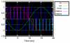
In this diagram the reference wave is 50Hz and my PWM signal is switching at about 350Hz. Though in a real system, I used a signal of 40kHz. This is just for clarity. You use the reference sinusoid, the inverted sinusoid, and a triangle wave to control when you switch on/off the various mosfets comprising an h-bridge. You can see how the pulse width is varied to correspond more or less to the amplitude of the sine wave at that point.
That is going to need some hefty parts to build esp the power capacitor and inductor. In any case, you will also need about 30A or so on the DC side which is pretty high for everything except maybe a car alternator and battery.
This site uses cookies to help personalise content, tailor your experience and to keep you logged in if you register.
By continuing to use this site, you are consenting to our use of cookies.