Hi --
I was learning (just on my own via Internet for hobby) about transistors and got interested in the Common Emitter Class A amp.
I realize that I cannot connect a speaker directly to this (gain would drop severely). I have seen many articles etc. on the Internet that show two concepts for overcoming this impedance mismatch problem. One is an audio transformer in place of the CE collector resistor. The other is using an emitter follower.
I tried the Emitter Follower...
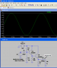
I did my calculations and was able to make a Common Emitter amp with Emitter Follower stage that when simulated did what I expected. I have attached my circuit.
Now I want to replace RL2 100K with a speaker as I have seen many places on the Internet. But when I do that the simulation shows a disaster (see attached pic with circuit and simulations).
It seems like from everything I have read that I should be able to do the following:
[Mic or Computer] --> [CE] --> [EF] --> [Speaker]
Can anyone provide guidance on this problem.
p.s. I understand this design may not be practical for real world applications -- but I am really just enjoying the CE and EF amps for fun and would like to go from simulation to breadboard and speaker. Then when that is learned maybe try some more practical amplifier circuits.
Thank you!!!
I was learning (just on my own via Internet for hobby) about transistors and got interested in the Common Emitter Class A amp.
I realize that I cannot connect a speaker directly to this (gain would drop severely). I have seen many articles etc. on the Internet that show two concepts for overcoming this impedance mismatch problem. One is an audio transformer in place of the CE collector resistor. The other is using an emitter follower.
I tried the Emitter Follower...
I did my calculations and was able to make a Common Emitter amp with Emitter Follower stage that when simulated did what I expected. I have attached my circuit.
Now I want to replace RL2 100K with a speaker as I have seen many places on the Internet. But when I do that the simulation shows a disaster (see attached pic with circuit and simulations).
It seems like from everything I have read that I should be able to do the following:
[Mic or Computer] --> [CE] --> [EF] --> [Speaker]
Can anyone provide guidance on this problem.
p.s. I understand this design may not be practical for real world applications -- but I am really just enjoying the CE and EF amps for fun and would like to go from simulation to breadboard and speaker. Then when that is learned maybe try some more practical amplifier circuits.
Thank you!!!
Attachments
Last edited:
") ! -- I appreciate all your ideas and help!
! -- I appreciate all your ideas and help!