Continue to Site

Welcome to our site!

Electro Tech is an online community (with over 170,000 members) who enjoy talking about and building electronic circuits, projects and gadgets. To participate you need to register. Registration is free. Click here to register now.

  • Welcome to our site! Electro Tech is an online community (with over 170,000 members) who enjoy talking about and building electronic circuits, projects and gadgets. To participate you need to register. Registration is free. Click here to register now.

how to connect a LED light to a switch?

Status
Not open for further replies.
ok i want to connect a LED light (or more than 1) to a switch for my car. Can some one please help me? Thanks!

PS~ im a no0b at this electronic stuff so please go easy on me!
 
ok ok!
you just waited 50 minutes. do you think that there is someone 24/7 to help you here?
ok. you could do this: conect a led in series with a 1K resistor and connect it to the power suply. if you want more leds just connect a resistor for each.
i will not post the calculations. if you search the forum i am sure you will find them a few dozen times. just look around........
 
Okay, well you got your power supply already (the battery) Now all you have to do is determine what kind of LED you want in it, if you want chasers (Knight rider lights) it'll be a bit more difficult, then you have to figure out how much power your car's battery puts out.

Then once you know what the voltage is of the battery, and you have an LED picked out, you have to get your resistor for the LED(s) You figure this out by finding out the voltage the LED can handle to get maximum illumination, what the draw of the LED is is (in miliamps, usually between 5 and 25), and what the voltage of the batter is, and calculate this equation.

R= (Vs-Vl)/I

R = Resistor Value in KiloOhms
Vs = supply voltage (Your Battery Voltage)
Vl = LED voltage (The Max Voltage of Your LED)
I = LED current (Miliamps)

EXAMPLE: So say your car is running a 12v car battery (average) and your maximum load of the LED is 4v, and it has a 20 mA draw, then your resistor value would be .4KO, or 400 Ohms.

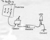
After that you need a switch, and you need to find available space on your dash.

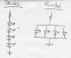
Wire up your circuit, and use your battery in place of the schematic battery. Now in your circuit before you place the resistor, and LED, run the positive (and possibly the negative depending on what type of switch you choose) to a hole drilled in the dash. Then place the LED wherever you want it, making sure your resistor comes BEFORE the LED.

If you plan on making a chaser LED, then I'll get you a link, unfortunately it's a 9v, so if you do have a 12v battery, which is normal, you'll need to get a 12v to 9v transformer or something similar.

https://www.aaroncake.net/circuits/chaser.htm

Got the idea ?
 
So you'd rather run it off a 110+ Volt Alternator, don't think that's a good idea at all.
 
It's a better idea, and much cheaper, in order to run it from the fuse box it'll probably cost you 10x more to get a 110->9v or so Transformer, and you'd have to run a line back to the alternator anyway, which is just by the battery, so spending $.10 more on a bit of wire is better than shelling off $5-20 for a transformer.
 
Nostrafus, I don't think elecwanabe means that they wants to run it to the alternator. I think they're talking about the 12V fuses, usually situated near the dashboard.
 
phasor's right......im talking about the fuse box on the dash. can someone please do a diagram of this? connecting the switch to the LED? i am a visual person......thanks for all these replies though!
 
Nosatrafus,
well, i understand that he wants to connect it to the fuse box from the car.....cause that's what he is talking about....is he?

and about the one that runs from 9V well....i think that it cn run from 12V too, or he coud use a LM317 reg...
as you thought about it.....with a transformer? /an even simple solution for the chaser will be to connect it trough 5 diodes, wich will be less expensive then the LM317.....but still.......he just wants a led so.......
 
Here it is, to put you out of your misery :lol:

You can add more LEDs, either in series or parallel with the existing one, but you will need to adjust the value of the resistor.
 

Attachments

  • LED_146.jpg
    LED_146.jpg
    16.4 KB · Views: 4,633
THANK U PHASOR!!!! Sweet Jesus.....that's all i needed to c lol. all i need to do now is find out what kind of resistor i need. do i use that same equation that u guyz gave me?
 
Yep
 
As I said, there are two schemes: series, and parallel. In series, they are hooked up head-to-tail, like a chain. In parallel, they are hooked up head-to-head & tail-to-tail. Take your pick - some people will argue the merits of one scheme over the other - for a small project like this, I don't think it matters which one you choose.
 

Attachments

  • seriesparallel.jpg
    seriesparallel.jpg
    15.7 KB · Views: 1,527
electronicswannabe, i think you'll find that it doesn't really matter what value resistor you use. you could use anything from a 220 ohm to a 1k and you'd be fine.

at least that's what i've found in my few months of messing around.

it's good to know the formulas anyway though.

ohms law is a good place to start
V=IR

good luck in your adventures!
 
Phasor,
i think that it matters wich one you choose. the series is better, if all the leds will be on when the engine is not running. it has a better efficency.
but if the leds are turned on when the engine is running, it really doesn't matter.
but you got to be careful, because at the paralel method, there will be much power lost on the resistor, so a 1/4W is not enough. you might need a 1W or more resistor type.
good luck :!:
 
Status
Not open for further replies.

Latest threads

New Articles From Microcontroller Tips

Back
Top