Continue to Site

Welcome to our site!

Electro Tech is an online community (with over 170,000 members) who enjoy talking about and building electronic circuits, projects and gadgets. To participate you need to register. Registration is free. Click here to register now.

  • Welcome to our site! Electro Tech is an online community (with over 170,000 members) who enjoy talking about and building electronic circuits, projects and gadgets. To participate you need to register. Registration is free. Click here to register now.

How to activate 12V/2A electromagnet with 5V (USB power) each 60 minutes?

Status
Not open for further replies.

Alan2017

New Member
Hi all,
I feel like I am stuck because don't know how to solve following "simple" solution:
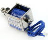
Somehow I have to (each 60 min) activate 12V/2A electromagnet, with 5V input voltage (tipical PC USB (5V/100mA).
5V is powering microcontroller, and with that microcontroller, each 60 min I have to activate 12V/2A electromagnet.
How to do that?
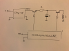
My Idea was (during this 60 minutes period) to charge capacitor using Step-up converter (from 5V to 12V) and when time comes, to disconnect RC (charging) circuit (with transistor), and with another transistor to activate LC (discharging) circuit.

Is there any easy way to do that (linear regulator, or something similar that already have all those switching electronic in one single chip)?
Thank you,
Alan
 

Attachments

  • circuit.png
    circuit.png
    255.4 KB · Views: 298
You forgot to tell us how long the electromagnet has to be powered each hour?

A second or so is easy; several seconds gets harder.
 
Last edited:
I looked at capacitors. Less then $20.00usd, that are in stock. I could not find anything that will work. 100,000uF 20V is too small.
My first try was to charge the capacitor to 15V and keep it on until it discharges down to 9V.
Maybe charge to 18V 3A and in one second the cap will be down to 6A 1A.
If you need the voltage to be held at 12V on the electromagnet, then we will need more parts!
Can you use a rechargeable battery?
 
Here is a concept:

Start with a 5Vin, 12Vout SMPS Boost Converter that has intrinsic current limiting. Say the output is limited to 100mA. Because such a converter is about 85% efficient, then the input current from the 5VUSB source would be 12*0.1 = 5*I*0.85, or I = 12*0.1/(5*0.85) = 0.235A, well within what USB can deliver. I model the boost converter as a 0.1A current source which switches off when V(out) >= 12V.

Use the boost converter to charge a 1F 12V super-capacitor. 100mA will charge 1F through 12V in 120s. Thereafter, the current drawn from the USB drops to whatever it takes to run the timer.

Make a timer that makes 5V for 1s every 3600s. Use it to turn on a power NFET switch that pulses the 6Ω coil with a snubber diode around it.

During the 1s the solenoid is driven, the supercapacitor discharges from 12V to ~10.5V. The current is most of the 2A you would expect.

Look to see what is available for the supercapacitor. If not a supercapacitor, a small NiMh or even NiCd battery pack might work. FleaBay and Banggood have various Boost converters.


35.png
 
I model the boost converter as a 0.1A current
I think the 5V is limited to 100mA so the 12V would be limited to 30mA.

I found a 1F 16V cap but it is $90.00. (US price)

supercapacitor discharges from 12V to ~10.5V
If you really want to get POWER out of a capacitor you need to "discharge" the cap. So make the change in voltage as large as possible. For example MikeMI's circuit has 1.5V change in voltage. If the change in voltage was 15V you would need 1/10 the size of cap.
Example: Charge the cap to 20V and discharge to 5V. Use a boost-buck power supply to make 12V for the load.
 
Yeah, I did some looking for 12V supercapacitors, and you likely cant afford them...., especially if you try to make a 12V capacitor bank out of 2.7V capacitors
So, I think that I would be looking for a 12V battery instead. I have some ideas about where to get a step-up converter if you want to pursue this... Since you have 3599s to recharge the battery before it is discharged, the boost converter could be made low-current so as not to overload the USB.
 
Dear both,

I do not know how to thank you enough for your great support and the way you dedicate your time to my problem!

Actually I was searching for solution on how to switch between charging and discharging capacitor, and thanks to you I just realized that there is a bigger problem that I didn't even dream about (I thought that 1 hour will be enough time to charge e.g. 1000uF capacitor, which will be able to fire a ball with push-pull electromagnet).

I don't think that if capacitor will be fully discharged would be a problem. I need a short and strong impulse that could activate a electromagnet and fire a ball.

I'll have to think about something else because I would like to avoid batteries and additional electronic taking care for charging those batteries.
I wanted simple solution, but it seems that there will be no any - or do you think that solution with batteries could be simple one?

Thank you
 

Attachments

  • electromagnet.PNG
    electromagnet.PNG
    660 KB · Views: 283
I'll have to think about something else because I would like to avoid batteries and additional electronic taking care for charging those batteries.
I wanted simple solution, but it seems that there will be no any - or do you think that solution with batteries could be simple one?

By FAR the simplest solution for would be to have a 12V battery, and simply take it away and charge it up periodically - the occasional short pulses means it would last a long time between charges. The micro-controller could be powered from that as well.

You're also making life complicated by puzzling about charging and discharging capacitors, there's no need to discharge it, simply trigger the solenoid briefly (you don't need anywhere near a second) and then un-trigger it, leaving the capacitor still partially charged.

If you don't want the simple 'take it away and charge it' solution, then you need an inverter to convert the 5V USB supply to 12V (or more) and charge the battery or capacitor bank.
 
Maybe I have complicated my project too much with this charge/discharge circuit?!
All I wanted is to avoid overloading of USB.

Based on all your suggestions, I guess that "Step-Up DC/DC Converter with input current limiter" might work.
I found some solution from Linear Technology "LT1618".
What do you think...if I connect 10000uF capacitor between +12V and GND, would be enough for that pulse of 2A to activate electromagnet?
12VBoostConverterWith500mA_InputCurrentLimit.png
I will experiment with pulse width (starting from 0,1 sec)
I hope that current limiter will not allow overloading of USB after capacitor will be discharged?
finalCircuit.jpg
Do you have any other suggestion or tip that I should take care of, or maybe some other step-up converter with current limiter?

Thank you all!
 
Why cant you use a spare 12V supply connector from inside the PC? bring the 12V line through a small hole in the case (likely an existing air hole). Power the micro via the USB, then when the time comes to fire the ball, use a optical isolator (or fet) from the micro to the solenoid which is powered from 12V already in the PC. Most PC's have spare connectors inside that you could snip the 12V line from (yellow normally).
 
If you use an adjustable boost converter with a simple resistor to limit current and the biggest capacitor you can afford and just adjust the output voltage until it fires the solenoid effectively. You could go as high as deemed safe (40V ish) to store enough energy to fire your solenoid. To get an idea of how much energy is required, use the weight of the projectile and the height required to find joules required and start from there.

Mike.
 
Converters etc and caps just seem a bit overkill and expensive, not disagreeing as the info is really limited. But KISS seems the most obvious and almost free.

Oh and be careful firing metal balls. replacement windows arnt as cheap as you think, or at least wasnt in my case :D
 
A boost converter doesn't seem like overkill to me. **broken link removed** are AU$1 (60p) on ebay and go up to 24V. The current will need limiting but that just requires 1 resistor.

Mike.
 
A boost converter doesn't seem like overkill to me. **broken link removed** are AU$1 (60p) on ebay and go up to 24V. The current will need limiting but that just requires 1 resistor.

Mike.
No fair play, I cant believe some of the prices lately! I was thinking more of making one etc etc etc, but for $1 already made it would make sense. I have so many components I usually make what I need, but its getting to the point where its so cheap to buy it isnt worth my time to make it. Sorry Mike I wasnt arguing, and I didnt realise they are peanuts to buy now.
 
If you use an adjustable boost converter with a simple resistor to limit current and the biggest capacitor you can afford and just adjust the output voltage until it fires the solenoid effectively. You could go as high as deemed safe (40V ish) to store enough energy to fire your solenoid. To get an idea of how much energy is required, use the weight of the projectile and the height required to find joules required and start from there.

Mike.
Thank you all for helping me with this project!
As much as all of you share your ideas, I have better understanding of how this project should be properly designed.
My mistake was in the beginning - I thought that I will need constant current of 2A within a whole second, but reading your posts I realized that I just need one short impulse of 0,1 second (or even less). I should experiment with pulse width - what will be a minimal pulse to fire a small light ball in the air.
Same for voltage - I will not need constant 12V.

Based on your suggestions, this will be my final project scheme:
finalCircuit2.png
May I please ask you to help me with:
  1. calculation of needed capacitor - there is no need for 1 second pulse (0,1 sec will be enough to trigger solenoid rated as 12V 2A).
  2. where to place currency limiter resistor (in front of step-up converter: resistor R1, or after converter:resistor R2)?
  3. If I place it as resistor R2 (after converter), it will delay charging of capacitor?
  4. Should I charge capacitor to higher voltage and to use step-down converter for the solenoid stepUp_StepDown.png ?
I will try to fire a small ball (weight: 200 g) 30 cm in the air.
Idea to use USB power is because it is widely available.

Thank you all!!!!!
Alan
 
I already showed you that if you charge the cap to 12V, you need most of 1 Farad if the pulse lasts 1s. If you think that a 100ms pulse will do, then you can get by with 0.1F.

This raises another issue: What is the inductance of the coil? I'm guessing about 20m to 100mH, so you also have to consider how long it takes to establish the current to get the solenoid's armature moving. You really need to do some tests. Here is the current through the inductor considering the rise time and the energy stored in various capacitors charged to 12V if the timer pulse lasts 100ms. The smallest pulse Lt.Green is with 1000uf (1mF). Red is 2mF (double), Green is 4mF (double again) and so on until 64mF:

You might charge the cap to ~30V, and then totally dump its energy into the solenoid. This might reduce the capacitor to a more manageable size and wont hurt the solenoid. Here are the current profiles for smaller capacitors charged to 30V. Lt.Green is only 100uF, increased by double each subsequent trace. The current pulse is bigger, but is shorter.


38.png
 
Some maths, the energy required to launch your ball is E=mgh (mass*gravity*height) = 0.2*9.81*0.3 = 0.6 Joules. A 10,000μF capacitor charged to 12V will hold 0.5* 0.01*12^2 = 0.72 Joules. Charged to 24V is 4 times as much = 2.8 Joules. However, as pointed out by MikeMI above, the problem is getting the energy into the solenoid quick enough. To calculate time available we need the launch speed, (from E=0.5*m*v^2) V = sqrt(0.6/0.2/0.5) = 2.5 m/s. Assuming a stroke of 5cm then the time available is (distance/average speed) t = (0.05/1.25) = 0.04 seconds.

So, something like a 10,000μF capacitor charged to somewhere between 12 and 24 volts will probably do the job. Personally, I'd get a capacitor and a lab supply and charge to different voltages to find the voltage that works. Note, in Mike's traces above the energy is the area under the curve up to 40mS. With the traces in mind the capacitance probably should be around 20,000μF.

Edit corrected the maths.

Mike.
 
Last edited:
Status
Not open for further replies.

Latest threads

New Articles From Microcontroller Tips

Back
Top