Jony130,
Congratulations Jony130! Jackpot! You have finally showed me definitive proof that the transistor will come out of saturation with the curves of fig. 16 of the ON data sheet. Brownout's circuit shows a Ib of about 0.5 ma and a Ic of about 115 ma. That is more than enough to increase the voltage by 0.69 volts and beyond, thereby establishing reverse c-b bias to bring the transistor out of saturation. It is amazing to see how the ON data sheet differs from the Fairchild one. The Fairchild does not even show Ib's, and does not show Vce rising much above 0.3 volts. That is not enough to bring it out of saturation.
By the way, the ping thumb filies you posted are useless to me because they are just that, thumbnail size. Unless you can tell me how to expand them, don't bother to post them.
I sure would like to read that material, but the thumbnail size precludes me from doing so.
As I said before, I don't trust that curve to analyze saturation. The Ib is relatively constant at 0.5 ma, and yet it shows a collector current of 70 ma at that value on the saturation boundary. The simulation shows a Ic of 117 ma. I don't think that hfe has any significance in saturation, because Ic cannot be controlled by Ib when in that state.
I have never said Vbe controls anything in the saturation region. I have always said that the Vbe causal control was for the active region.
Ratch
According to the Fairchild data sheets, the transistor can easily exist in saturation at 500 ma, so just increasing the current to 120 ma is not going to hack it. From ONsemi datasheet it's clearly shows that if IB is equal 600uA then BJT is comes out of saturation for Ic > 100mA
[URL="https://static.electro-tech-online.com/imgcache/9977-86_1282127414_thumb.png"]https://static.electro-tech-online.co...7414_thumb.png[/URL]
https://www.iele.polsl.pl/elenota/ON_...r/2n4401-d.pdf
Congratulations Jony130! Jackpot! You have finally showed me definitive proof that the transistor will come out of saturation with the curves of fig. 16 of the ON data sheet. Brownout's circuit shows a Ib of about 0.5 ma and a Ic of about 115 ma. That is more than enough to increase the voltage by 0.69 volts and beyond, thereby establishing reverse c-b bias to bring the transistor out of saturation. It is amazing to see how the ON data sheet differs from the Fairchild one. The Fairchild does not even show Ib's, and does not show Vce rising much above 0.3 volts. That is not enough to bring it out of saturation.
By the way, the ping thumb filies you posted are useless to me because they are just that, thumbnail size. Unless you can tell me how to expand them, don't bother to post them.
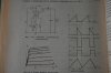
And here you have the photo from very old Polish book writes by professor Jerzy Baranowski in 1976r.
[URL="https://static.electro-tech-online.com/imgcache/9978-47_1282127008_thumb.jpg"]https://static.electro-tech-online.co...7008_thumb.jpg[/URL]
Where he describes the principles of operation self oscillating DC to DC converter.
And he also start in the saturation on the left of the base current line.
Why? Becaues IB is still 600uA and Ic is less then 100mA, and all VCC voltage is across the coil. So BJT is in saturation.
I sure would like to read that material, but the thumbnail size precludes me from doing so.
Why current stop in 120mA. Well the answer is simple.
We have two factors that cause Ic current to stop from rising even more then 120mA.
The first factor is obviously the base current.
See this Ic = f (Vce) for Ib=const
https://static.electro-tech-online.co...1281988250.png
And of course LTspice confirm this to
[URL="https://static.electro-tech-online.com/imgcache/9979-63_1282131884_thumb.png"]https://static.electro-tech-online.co...1884_thumb.png[/URL]
The second factor which decide the final value of Ic current is BJT it's self.
And in particular the current gain (Hfe).
As I said before, I don't trust that curve to analyze saturation. The Ib is relatively constant at 0.5 ma, and yet it shows a collector current of 70 ma at that value on the saturation boundary. The simulation shows a Ic of 117 ma. I don't think that hfe has any significance in saturation, because Ic cannot be controlled by Ib when in that state.
And it's really funny to insist that Vbe is the control force, becaues even in simulation if IB remains unchanged (600uA).
And we will only change the Hfe of a BJT the sat. Ic current will be changing.
And I do not have a problem to change my point of view between (VC/ CC model) for BJT depending on which "model" better fits to the circuit.
I have never said Vbe controls anything in the saturation region. I have always said that the Vbe causal control was for the active region.
Ratch
")
