MrAl,
You are making my point for me by listing all those currents. Neither Ic or Ib determine saturation or not. When Vcb is zero or less, and the transistor loses its reverse bias, it will go into saturation. Ib and Ic don't affect saturation unless they pull down the reverse bias. Do a differential voltage measurement between the base and collector. You will find its zero point syncs perfectly with whether the transistor is saturated or not.
Why are we talking about ideal coils? The coil has resistance, as does the voltage source and the transistor. That establishes a current limit. The coil's back voltage eventually becomes close to zero as it approaches its current limit.
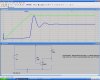
By disconnecting the capacitor, I see that the transistor operates permanently in the active region with no excursions into saturation. I surmise that on startup, the capacitor momentarily sends Q2 into saturation by making its collector the same voltage as the base of Q1 (0.7 volts). Then it latches and stays in saturation until the back voltage across the coil decreases.
Ratch
Brownout:
Sorry, i meant that happens with a resistor given that we increase the voltage as in one of the experiments i posted.
Check it out that way and see what you think.
Ratchit:
Yeah, dont try to turn it around to make your own point.
You keep saying Vcb and i already agreed with you, but it takes Ic to get to Vcb that you talk about. You just dont see it and you never will.
We talk about ideal coils when the resistance in the coil is low enough to be considered with no resistance. The theory goes with either some resistance or no resistance and you are the only one saying now you dont want to work with zero resistance. Look at it this way, 1.4 ohms would draw 3/1.4 amps at 3 volts which is at least 2 amps. The transistor wont allow that, and it is not the inductor series resistance that limits the current! If you think so, lower the resistance more then to 0.01 ohms. That's 3/0.01 amps, which the cells would not be able to supply, yet their minuscule series resistance (0.2 ohms) wont limit it either: 3/0.2 is 15 amps. That's not limiting.
The coils voltage does not really have to go to zero it just has to conduct more current, and 2 amps is pretty high already, yet it never gets there. Why? If that was the current limit then the transistor would see 2 amps, yet it doesnt. Why?
By disconnecting and operating as you say, you are working with a different setup then. You have to stick to what the transistor actually gets no matter what circuit you use. By using the correct circuit(s) you will see the transistor behave no matter what circuit you choose. By chosing the wrong circuit or different operation, you wont see it happen the same way. The circuit has to start from low current as the real circuit does if you are to use a different circuit, not from full supply voltage.
You just wont see this no matter what anyone says because you are only looking for ways to proved whatever it is you want to try to prove, which im not even sure what that is.
I already agreed with you about Vcb yet you keep bringing that up again. Without Ic Vcb can never rise. Try it, try to get Vcb to rise without increasing Ic at the point of operation where it matters.
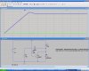
Also, run the osc circuit as it should run and look at the collector current and bias on the base of Q2. The collector current increases, it's Vce rises, the transistor comes out of sat, and that means Vce rises more, fed back through the cap Q1 turns off, that turns off Q2. Look at the simulation you run and look at the one i posted. It's pretty clear.
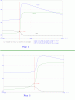
Look at Jony's post! That plot shows Vce vs Ice. Now try to get out of that one
")
If you increase Ice (as the graph y axis) you see the sat voltage rise and then break out of sat at the knee(s).
Try to argue against that one.
This is exactly what i had been talking about here, and this shows how the circuit forces the transistor out of sat.
Like i said, if you want to 'detect' Q2 coming out of sat with a measurement of Vcb, that's fine with me, but it will take increaseing Ice as in that plot to get it there. You're going to have to acknowledge this sooner or later.
Since you dont want to acknowledge anything anybody else has to say about this, we'll have to start listing this discussion point by point, and since you are arguing against we'll list them by your points and see what we get.
Your Point 1:
The series resistance of the coil limits the current.
Counter point proven:
No it doesnt, because its resistance is too low, 1.4 ohms, which is 2 amps and the transistor never gets there.
Your Point 2:
The series resistance of the batteries limits the current.
Counter point proven:
No it doesnt, because their resistance is too low, 0.2 ohms, and that would be 15 amps and the transistor never gets there.
Your Point 3:
The series resistance of the cells AND the coil limits the current.
Counter point proven:
No they dont, because their resistance together is 1.6 ohms, which is roughly still close to 2 amps and the transistor never gets there.
Your point 4:
The Vcb is an indicator of the saturation state of the transistor.
Counter point:
None, agreed.
Your point 5:
The Vcb takes the transistor out of saturation itself.
Counter point:
Not really, but partially agreed because it's too hard to prove otherwise, but in any case Vcb can only get to the required value by an increase in current Ice.
Your point 6:
It's Vcb that takes the transistor out of saturation itself, not Ice.
Counter point:
You can not EVER reach Vcb required unless you increase Ice.
Your point 7:
You dont have to increase Ice because of the feedback which cuts off Q1 and hence Q2.
Counter point:
Q2 comes out of saturation before the feedback arrives at Q1, as proven by simulation. In fact, if you look closely at the simulation you can see the transistor behaving exactly as Jony's plot of Ice vs Vce indicates it should. You can see the Vce start to rise BEFORE the feedback arrives at Q1.
Your point 8:
You dont agree with Jony's plot of Vce vs Ice.
Counter point:
It's a simple two dimensional plot that the manufacturer supplies to show typical operation of the transistor.
Your point 9:
The transistor region of saturation includes Ic of 100ma and even higher, so the transistor would stay in saturation.
Counter point:
You can not conclude that the transistor stays in sat unless you know Ib also, and given that Q1 is fully turned on, Ib will be constant and will not change until the feedback arrives. The transistor operates at constant Ib and it's only Ic that changes.
Your point 10:
The general operation of the osc circuit is that something other than Ic causes the rise in collector voltage and therefore the rise in Vcb.
Counter point PROVEN:
It is actually Ic that causes the rise in Vce which causes the rise in Vcb. To prove this, we only have to look at the simulation and take it one microsecond at a time. The simulation clearly shows that the transistor Vce starts to rise BEFORE the feedback gets high enough to cut off Q1. To make this more clear, we can use another circuit that has no feedback, or even simply short out Q1 collector to emitter to keep Q2 turned on constantly. What we see is as we turn the circuit on is that the collector current rises as the inductor allows with time, and it continues to rise until the transistor starts to come out of saturation. Lo and Behold, the transistor comes out of saturation even with no feedback...what a surprise