MrAl,
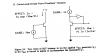
A circuit diagram is a specialized drawing that would not help in describing my viewpoint.
I think you get rusty on things you have not looked at for quite a while, but your cognitive skills should not deteriorate until you get very old. Also you now have more experience.
You are right, I got ahead of myself, so let me clarify. The coil is not DC coupled to Q1 due to the capacitor linking the two.
During the increase of current in Q2, the magnetic field builds up, and the coil opposes the B+ voltage. After saturation is reached, the current increase stops, and the coil stops opposing the B+ voltage. So the saturation current is constant, the voltage across the coil is zero, the magnetic field is present, and the base of Q1 receives a positive voltage, which cuts off Q1 and Q2. This stops the existence of the current in Q2 and L1, and that will cause the magnetic field to collapse and sustain a positive voltage on Q1 for a time.
Ratch
Hello again Ratchit,
Well, I dont know what makes you think that the saturation current has to stop rising. With the transistor CE shorted out and Resr of the inductor zero, the current would rise to an infinite level. Obviously this cant happen, so something has to give. Now if the transistor CE was a fuse instead of a transistor junction that fuse would blow and that would cause a halt to the current. Incidentally, the 'collector' voltage would also rise sharply once the fuse blew out, and that would couple through the cap and cut off Q1 (once, but it would ha ha).
Now this might seem somehow coincidental, so lets take Q1 out of the picture by shorting that out collector to emitter. That puts a constant bias on Q2, and it's collector current rises as the circuit is switched on. Now the current reaches the saturation point of the coil, and it starts to draw a ton of current, and that current does not increase gradually but very sharply. The transistor CE is now conducting heavily, but the current still increases. Eventually it reaches a point where the coil is conducting so heavily that the current gets to a point where the transistor saturation voltage starts to rise a little. It's still in sat, but it's Vsat starts to rise. With more time, the current goes even higher, until the Vsat reaches the max it can be and still be called "in saturation". Next the current continues to rise, but we've exceeded that breakpoint and the transistor starts to come out of saturation. All the while the current is increasing sharply too, and the transistor CE voltage increase sharply. Eventually the coil looks shorted and the transistor is conducting heavy current but it's Vce is almost as high as B+ itself. The transistor is now dropping all of the voltage so Vce=B+ and it is definitely out of saturation. Nothing else happens because we shorted out Q1 collector to emitter. If we hadn't done that, the sharp rise in collector voltage would have been felt through the capacitor and into the base of Q1 which would cut it off, which would in turn cut off Q2, and collector current in Q2 would die down fairly quick. That action of course causes a high back emf from the coil.
A second experiment is where we connect the transistor Vbe to a voltage source of about 0.8 volts, and connect a 5 ohm resistor from the collector to B+, and emitter to ground. As we increase B+, we see the transistor Vce rise following the rise in B+ until it reaches saturation, and then the Vce levels off, but as we increase B+ even more at some point the CE breaks out of saturation and the Vce starts to rise also, following the rise in B+ almost exactly (with a drop).
In other words, we can still force the transistor out of saturation even though we hold the input of the transistor Vce at a fixed level, in this case 0.8 volts.
That's an experiment you can easily perform in a circuit simulator with say a 2N2222A.
A third experiment is where we connect the same circuit, but instead of a 5 ohm resistor we use instead an inductor with low esr like 0.1 ohms. Now the behavior is time dependent (like the oscillator) where the collector rises more and more and more until the transistor breaks out of sat.
This cane also be done very easily in a circuit simulator with say the same transistor and say a 100uH inductor.
Both of these are very interesting to do and dont take much time.
BTW the circuits that Jony posted illustrate the same basic principle of more or less Vbe control vs Ic control.
OH yeah, another little experiment with this circuit is to increase the inductors Resr higher and higher. What happens is proof that it works according to the above. When the Resr reaches the level where the current can not get high enough to pull Q2 out of saturation (it limits it by Imax=V/Resr), the transistor Q2 'sticks' in saturation and the oscillations halt. This actually occurs at a value of Resr that would seem to allow everything else to work properly had it worked on some other principle, but it doesnt.
")