Continue to Site

Welcome to our site!

Electro Tech is an online community (with over 170,000 members) who enjoy talking about and building electronic circuits, projects and gadgets. To participate you need to register. Registration is free. Click here to register now.

  • Welcome to our site! Electro Tech is an online community (with over 170,000 members) who enjoy talking about and building electronic circuits, projects and gadgets. To participate you need to register. Registration is free. Click here to register now.

Hijack signals from scale lcd

Status
Not open for further replies.

dion

New Member
Hi,

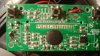
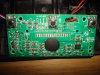
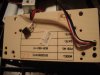
I am very ew to electronics and need some help hijacking the signals from a cheap kitchen scale I bought. I realise that the signal from the scale is analog, and intercepting the signal to the lcd would be easier. Problem is, I want to display what is show on the lcd, on my pc, as I want to manipulate the readings ie average etc). How do I interpret the signals from the pcb. Do I use th RS232 port? The lcd pcb has 16 connectors connecting to the lcd, and the characters are fairly big(1 line of chars).

I have googled for info on the lcd model no. M1094-10TR, but found nothing. I would like to log the input from the lcd connectors.

Many thanks,
Dion.
 
A raw LCD will have an apx 40-100Hz backplane signal as well as a signal lead for each visible segment and symbol on the LCD. Segments/symbols are driven out of phase to the backplane when ON and in-phase when OFF. A LCD with a built in driver, which is probably what you have, is another story all together and you'd really need the data sheet on the LCD for that.
So what you really need is a microcontroller to interpret this data, convert it to ASCII, and send it to your PC via RS232 or USB. You could also do it via the parallel port and discreet logic, but that would be much more difficult.
 
Last edited:
How about taking some really good pics of the PCB and posting them? We might be able to make some more informed suggestions then. You may very well be able find a better signal on the scale board than the LCD will provide.
 
Pics

Thanks for the reply guys. I will get hold of a decent camera and send pics. I like the idea of hijacking the signal directly from the scale outputs. I just need to find info on what I will be receiving as input from the 4 wires leading from the scale, as well as how the scale actually works.

dion.

Most now a days use a 4 wire load cell resistance bridge. Two of the wires are used to 'excite' the bridge, typically using 10volts or 5 volts, but in your case they probably use less as the battery voltage is sure to be much lower. This excitation voltage must be regulated. The other two wires are used to measure the differential voltage generated from the weight on the load cell. It's just millivolts in value and needs amplification with an op amp.

Lefty
 
You could use a webcam, and some OCR software functions to get the values onto the computer.
 
Sorry for the long delay. Here is the image.
 

Attachments

  • DSC01339.JPG
    DSC01339.JPG
    908.7 KB · Views: 285
If you're lucky the amplifier for the weight sensor signal is not underneath that blob. You'd have to probe around with an oscilloscope or a multimeter while pressing up and down on the scale to see if you can find a trace that carries the analog signal, which you can feed into your own ADC and log it that way. Looks like the row of pins above the blob in the picture is the LCD connection if you still want to go that route, but that picture is so blurred and you didn't take one of the other side of the board it's hard to tell anything.
 
Sorry for the long delay. Here is the image.
Use the macro function on your camera (Usually a flower icon) so we can see the PCB better. Do the 4 wires on the left go to the load cell? What is the part number on the 8pin SMD IC?
 
The 4 wires on the left do attach to the load cell. I have attached 2 more pics. Any ideas about an ADC?

Thanks,
Dion
 

Attachments

  • compressed photo 2.JPG
    compressed photo 2.JPG
    319.8 KB · Views: 294
  • compressed photo 1.JPG
    compressed photo 1.JPG
    223 KB · Views: 275
IF I recall it correctly a simple high input resistance op amp (Jfet inputs) should be able to directly read the millivolt signals coming off of the load cells and be able to amplify them.

After that a simple single channel analog signal monitoring unit will send the right information to any off the shelf data logging or monitoring type software you use.
Some analog data or signal collection devices are capable of direct measurement from standard load cells too!
Look for commercial or industrial data logging systems for more information. They are very common in manufacturing. You may end up with a complete plug in and go set up!
 
It looks like the sensor wires ( S+ & S- ) go straight into the epoxy blob IC. You could measure the voltage between S+ & S- for different weights and then use a differential amplifier to reference the voltage to ground for your ADC. It looks like the calibration table is stored in U2 so the output of the load cell may, or may not, be linear. How much resolution do you need?
 
I am a little out of my depth here. My strength is in app dev, so please be a little patient. If I do not respond fairly quickly, I am more than likely researching the concepts you guys use. What exactly do you mean by resolution in this context? The accuracy of the reading?

Thanks.
 
>> It looks like the sensor wires ( S+ & S- ) go straight into the epoxy blob IC...
If you mean the 4 wires from the load cell, they do not go directly into the epoxy blob IC, but are soldered onto the pcb on the left(look at the first of the last images attached previously).
 
Yes, but the wires enter the PCB, go through 2 zero Ω jumpers and into the epoxy blob. There are some bypass capacitors in parallel to the lines (And maybe some resistors- can't tell from the image), probably shunting noise to ground, but the traces on the PCB appear to go straight from the wires to the blob. ie: There is no OpAmp between the load cell and the blob.
What exactly do you mean by resolution in this context? The accuracy of the reading?
By resolution, I meant how much precision do you need. ie: a 10bit ADC will give you 1024 discreet steps.
 
Last edited:
At this point I am more concerned about the method than accuracy or precision. So whatever is going to ease your explanation of converting a analog signal from the load cell to a digital equivalent on my pc which I can display on the screen using any of the RAD IDEs available, would be fine with me.

Thanks again.
 
If by RAD you mean Rapid Application Development, then you'll have to decide which RAD IDE you are going to use first. The only thing like that which I am familiar with is LabView. For LabView you can get analog signal acquisition modules which come with LabView specific drivers. Something more generic like Visual Basic may work also but you'll need something standard, like a USB virtual COM port and microcontroller, to interface to the computer.
By the sounds of things, you need a prebuilt solution, which is very RAD specific.
EDIT: you could search for an analog data logger project to interface with your scale.
 
Last edited:
I am sure thst the displaying of digital values on a pc screen is not too big a deal no matter which RAD is used.

If you have the time, can we divide this task into steps so that I can research to better understand any advice/referrals and direction fom yourself, for eg, what is the next step in reaching the end goal: amplification (how) of the signal from the 4 wires so that a pic can detect the signal? Then write pic(c) software to interpret the signal? Then push the massaged info to pc through an rs232 as numbers?

I hope I make sense.

Thanks.
 
For the next step, amplification, we need to know:
What are the voltages on E+ S+ and S- relative to E- (ground)?
How much does the voltage between S+ and S- change between nothing on the scale and the heaviest object on the scale? You'll need a voltmeter that can read in the millivolts for this.
From this info we can design an amplifier to boost the signal to a 0-5V range suitable for a PIC's ADC input.
 
Last edited:
I eventually want to port the whole project back to a pic based system with lcd and keyboard. My understanding of pic programming is not advanced enough yet to do this, but I am working on a few simple tutorials. Electronics is also fairly new to me.
 
Status
Not open for further replies.

Latest threads

New Articles From Microcontroller Tips

Back
Top