Continue to Site

Welcome to our site!

Electro Tech is an online community (with over 170,000 members) who enjoy talking about and building electronic circuits, projects and gadgets. To participate you need to register. Registration is free. Click here to register now.

  • Welcome to our site! Electro Tech is an online community (with over 170,000 members) who enjoy talking about and building electronic circuits, projects and gadgets. To participate you need to register. Registration is free. Click here to register now.

Higher Voltage: Fool Your Alternator?

Status
Not open for further replies.
The voltage on the rotor with these regs is a sawtooth CRO set at 5mv/div & sweep 1ms/div. This one is the adjustable one ive done the circuit of.
ADJ REG.3, 5mv-1ms.JPG
ADJ REG.1.JPG
ADJ REG.2.JPG
 
BOSCH REG.3.JPG
BOSCH REG.1.JPG
BOSCH REG.2.JPG
BOSCH REG.3.JPG
BOSCH REG.1.JPG
BOSCH REG.2.JPG
This is the reg for the Bosch altenator in the previous article. CRO setings 5mv/div sweep 1ms/div.
 
Some measurements:
Temperature measured with Fluke IR thermometer.
Voltage measured with Fluke 77.

2000 GM vehicle; Just started; alternator temp: 25 Fahrenheit ; Voltage at battery: 14.3 V idle; 14.3 V Revved

2000 Toyota Vehicle;
Just started; Alternator temperature: 26 F 14.3 Idle; 14.2 Fast idle
Idle for 20 min; Alternator temp 125 F; 14.13 V; 14.13 V revved.


Hi again,

Thanks for the readings. This confirms that it should be above 14.0 volts when charging normally. I am pretty sure now that this is better than just 14.0 or something low like that.
 
This is the reg for the Bosch altenator in the previous article. CRO setings 5mv/div sweep 1ms/div.


Hi again,

Thanks for the scope pics. So it looks like they turn it on and then turn it off, or that could be because there is no drive signal between peaks. Very interesting.
 
...
Mike:
The diode physical size seems to have a lot to do with the current rating, and the diodes i've seen that were 3 amp were much bigger than similar ones that are rated only 1 amp. With that in mind, the diode trio in my alternator has three diodes with body length about one half the length of a 1N4004 series diode and about the same diameter, so they are smaller than a 1N4004 diode. That makes me think they are only rated for 1 amp, but i could be wrong of course as i can not see a number on them.
All nine of the diodes are in intimate thermal contact with a heatsink, so they are rated quite a bit higher than you think. The six big ones are rated so that the main alternator output can be 60A, and the trio has to produce the rotor excitation current of 2 to 3A max.

One other interesting thing though is that the driven winding measures 3 ohms with nothing else connected (shaft removed from the alternator and measured directly on the slip rings).
The six larger size diodes used for the main three phase rectification are surface mount and quite large rectangular shaped.

Various alternators I have measured the rotor resistance is usually between 4 and 7 Ohms.

I thought about completely rebuilding the voltage regulator section but im not sure i want to go that route because of the environment it has to run in, under the hood, and im not sure i want to run wires from the alternator all the way into the passenger compartment as that would be about a four foot run.
Granted it would be really nice to be able to adjust it for whatever i wanted it to be.

You can buy a generic external VR and modify it to any voltage easily. Just notice if one of the rotor brushes is permanently tied to Gnd or B+, and get either a type A or type B VR as needed.

When you said 'bypass' the regulator, did you mean remove the old one completely and replace it, or just use a permanent fooling regulator that just electrically bypasses the old regulator?
I ask because i cant remove the regulator because the housing also holds the brushes, but i could possibly see using a parallel circuit to the regulator that drives the low end of the coil, and that would effectively take over.

You would have to retain the brush holder, but disconnect the potted-in VR. That is possible.

One more little question, do you know if the coil in these things is driven in a linear way or bang bang just on or jsut off? The linear way would push a very variable current through the coil, which might range from 100ma to 3 amps (or whatever the top end is) while the bang bang would just turn it on and off.

Go back and study the sim I posted way back. The Bosch schematic is consistent with the bang bang method. The switching transistor does not have adequate heatsinking to be a linear regulator. Notice the positive feedback around what is a Schmidt Trigger in Debe's schematic.

Oh yeah one more thing, the old alternator looks like it has the slip rings all carbonized. I wonder if that is why it stopped working. It worked intermittently for a while before it stopped altogether.

Assuming the bearings are ok (usually replaced at the same time), you can get a new set of brushes inexpensively at the EBay store I linked you to... I have personally rebuilt many alternators. They are easy to get going again...
 
Hi,

Thanks for all the info Mike, it will come in handy soon i think. Still experimenting a little right now.

Yeah i thought that rotor winding resistance sounded low too, but then 3 ohms isnt that far from 4 ohms.
This was from a failed alternator, so who knows what went wrong with it. I have a feeling it was just the slip rings.
 
...
This was from a failed alternator, so who knows what went wrong with it. I have a feeling it was just the slip rings.
More likely a simple brush replacement will fix it...
 
For brush replacement, the alternator will come apart, but may not be obvious how to put it back together.
Do mark the case, so it goes back together the same way.

You usually need to insert something like a paper clip, into the brush holder captivating the brushes. Then assemble and remove the pin from outside the alternator.

It looks as if, you need to determine if the positive side of the rotor is switched or the negative and obtain access to the switched side.

Once you have access, your own regulator can "OVERRIDE" (Make the voltage higher) the built-in one.
 
Hi,

Thanks again guys.

Yes, i ran into the brush problem before, where you cant get the armature back in without depressing the brushes and holding them there with a thin straight 'pin' like object, for which i used a very small hex key wrench.

The reason i thought it was the slip rings at fault in the old alternator was because they were very very brown not shiny, and the brushes do protrude out from the housing when the armature is removed. I guess it could be that they dont put enough force on the slip rings anymore so the slip rings got carbonized. I cant be sure yet though.

I think this is one of those "ground control" types where the coil gets grounded or at least partially grounded to energize it. That's partly because i think a while back i traced one of the brushes right to V+ of the diodes. The only thing i dont like here is that many of the resistances are very low, so it's not as clear if something is connected or just low resistance. As i said, the armature coil measures only 3 ohms.

I think i can find this 'control' ground connection too but it might be a guessing game because the housing for the brushes is all one solid piece of some type of plastic or something. It's hard to figure out what the other brush goes to (what connection) because there is no breakout other than four connections on top that dont go anywhere. Maybe they are there for factory testing, and maybe one goes to the other brush, but it's hard to tell for sure.

Here's a pic, where you can see the brushes and the housing with the four soldered 'connections' on top. You can also see the three small diodes to the left of center, which are unequally spaced apart.
 

Attachments

  • AlternatorView-1.jpg
    AlternatorView-1.jpg
    183.5 KB · Views: 471
Last edited:
That's a "pretty sick" alternator.

I believe your problem is the brush holder. Look at the top right pic where the bar is. I think the brush holder wiggles, because the insulator is broken. The insulator should be concentric.

Note the uneven brush wear, further confirming the brush holder position. It's at an angle.

The brush holder is cracked where it encircles the shaft.

It looks like a washer on the top of the diode bridge stuck.

The solder joint of the opposite side is yucky too.

This https://www.alibaba.com/product-detail/Voltage-Regulator-2310002-E16-For-HYUNDAI_60096783250.html regulator looks "similar" to yours, and no cracks.

There are some cracked insulators on the left hand side, but they probably don't matter.

Who knows what other damage you have.
 
Last edited:
Hi,

I dont see any cracks anywhere. Im not sure where you are saying there are cracks.

The 'washer' may be there because i took the picture right after i took the assembly apart and did not move the washer away from the unit. So it's probably just resting there. I put it back together, but i can get it apart again.

This is the first alternator, the old one, that had been in the car for about 11 years. The 'new' one is in the car right now, and that is the one that is questionable. I know the old one doesnt work, but it is interesting to hear ideas about why it stopped working. Yes the brushes look worn, but if you saw the slip rings you'd be startled about how 'brown' they look. Maybe the brushes were not making good contact and that messed up the slip rings. The rings can be polished quite easily however.

I tested the new alternator yesterday when i went out for some things. With the lights on, heater on, rear window defroster on, and wiper on, the alternator can not put out enough voltage to charge the battery when idling at 1000 rpm (lower than normal). But as the rpm comes up, the voltage does go back up to around 14v or just under that.
The older alternator i dont think did that as it was probably a better quality unit when new. That thing kept the voltage dead solid no matter what i turned on. So i might be dealing with a cheap azz alternator (the new one) now.
 
Follow the cylindrical piece that goes around the shaft. It is split at the top left corner of the brush holder. Dunno, if it's supposed to be.

Above the two solder joints on the top of the brush holder, there is a round insulator. It's missing a chunk out of it.

Each brush should be worn symmetrically.
 
Hi again,

Yes i think the 'split' is supposed to be there.
I'll check the insulator.
The brushes are old so maybe they wore slightly differently, but the picture is a little deceiving too because it's at an angle that would make the lower brush seem longer. It may be a little longer though, i'll double check.

I guess i dont really have to use that old alternator anymore but i may want to modify the new one.

Thanks again.
 
Hi,

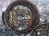
Thanks for the notations on the pic, which help point out the locations you were talking about.
Remember this is the old alternator so i dont actually have to get this up and running again, at least i hope not :)
But it is a thought, because that alternator worked pretty well when it did work. I had to get that alternator from a garage which charged a lot for the replacement/labor, which was over 300 dollars USD. The alternator did work great though for 11 years. The funny thing though is that i only use that car about twice a week to go less than 10 miles per week over that 11 year period, and yet the alternator guts look like that. Clearly the brushes are worn as you said. So the only good thing then i guess is that it put out the right voltage all that time.

But really i was asking about modifications to an alternator, what people were doing to get more voltage out of their alternator or possibly other modifications. I think it would be interesting to get it to put out more voltage so older batteries last longer too.
I noticed that in the winter months the voltage comes down a little naturally. That might allow this alternator to work better during that time. I also noticed now that it MAY go up to 14.2 volts when i first start the car, but then soon after that it comes down to about 13.8 or 13.9 volts. I would rather it stay higher, or start out higher and then drop to 14.2 as that would be MUCH better for my driving habits.

I will be trying the new battery soon too, so i'll see how that works over several weeks. Should be interesting.

I'll get some better pics soon too and post them so you can get a closer look at the old alternator. I am pretty sure that the 'crack' in the round part is supposed to be there, as it is not jagged but has smooth edges everywhere so it looks like it was made that way.
Not sure yet about the insulator though, i'll need to look at that again.

I ended up with a lot of things to do over the holiday so im trying to catch up on the 'regular' stuff so i can get back to this. So many things came up this year that have to be done first. Still trying to get used to a new keyboard also which misses letters sometimes when you type.
 
As Mike said, you only have two choices of alternator styles:
1) ground is modulated to the rotor.
2) +12 is modulated to the rotor.

Now, you need access. There were some solder joints on the brush holder. Dunno about the other side.

a) You either move the regulator external.
b) You just override the regulator - bring a single brush terminal external.

It would seem so much easier to design an alternator to modulate ground because +12 ign would be attached to the rotor and controlled by the ignition switch and it gives a relatively low current wire (3 A max or so) to sense the "system voltage".

IF it's the alternator where +12 is attached through the connector to the ignition switch, them you should have continuity between one of the brushes and that terminal. You would then need access to the "other brush:.
 
...
It would seem so much easier to design an alternator to modulate ground ...

Besides there are many more NPN or NFETs available than PNPs or PFETs. Low-side switching is easier than high-side switching...
 
As Mike said, you only have two choices of alternator styles:
1) ground is modulated to the rotor.
2) +12 is modulated to the rotor.

Now, you need access. There were some solder joints on the brush holder. Dunno about the other side.

a) You either move the regulator external.
b) You just override the regulator - bring a single brush terminal external.

It would seem so much easier to design an alternator to modulate ground because +12 ign would be attached to the rotor and controlled by the ignition switch and it gives a relatively low current wire (3 A max or so) to sense the "system voltage".

IF it's the alternator where +12 is attached through the connector to the ignition switch, them you should have continuity between one of the brushes and that terminal. You would then need access to the "other brush:.


Hi,

Very good, that's what i was thinking too. But i had one small worry...let me explain.

First, i figured maybe bring the wire out like you said, by soldering to the regulator which i think i can find the right terminal for, and you confirmed this now.
Second, once i bring the wire out and install the alternator i think i should be able to ground that wire to force the alternator to put out the max, which would not be much more than usual at idle speed because this is a small alternator. This would eventually go to say an NPN collector or as Mike said an N channel MOSFET drain, which would be nice too.

My worry is with the second thing there where we either connect right to ground temporarily or we use a transistor to ground for nice control. How do i know that they are not limiting the 'on' time so that the average current through those three small diodes is limited? If i connect right to ground an leave it there for a while (to charge a little more for awhile) then the diodes are working full time, which may be ok but i cant be sure. Maybe it would be better to pulse it with some duty cycle, because maybe that is what the normal regulator does? How can i be sure it wont blow something?
 
LUCAS 13TR reg2.jpg
This is another option, its a Lucas altenator regulator that was built in the altenator I rev engineered. To make it adjustable put a trim pot in place of R1,2 &3.
 
Status
Not open for further replies.

Latest threads

New Articles From Microcontroller Tips

Back
Top