Continue to Site

Welcome to our site!

Electro Tech is an online community (with over 170,000 members) who enjoy talking about and building electronic circuits, projects and gadgets. To participate you need to register. Registration is free. Click here to register now.

  • Welcome to our site! Electro Tech is an online community (with over 170,000 members) who enjoy talking about and building electronic circuits, projects and gadgets. To participate you need to register. Registration is free. Click here to register now.

High Side Transistor Switch

Status
Not open for further replies.

Mity Eltu

Member
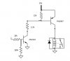
I have built a 2 transistor switch to be used on the high-side of a 24V DC relay (Circuit is attached). I have tested it and it works great, but I have a question. With regard to the diode across the relay. Does the diode need to be physically directly across the relay coil? Is it acceptable for it to electrically connected that way, but not in close physical proximity?

The reason I'm asking is that I'm building small breakout boards for the circuit to make circuit setup easier on a breadboard. I'm considering mounting the diode to the breakout board such that is will be electrically connected just as in the circuit, but physically it will be connected a few inches away. I just want to make sure I'm not about to violate some 'law' of relays or something.

What do you say?
 

Attachments

  • circuit.jpg
    circuit.jpg
    21 KB · Views: 174
No diode at all: bad.
Diode at collector/drain of driver: better, especially if the distal relay coil is fed with a twisted pair.
Diode directly across relay coil: best

Why do you need a high-side driver; wouldn't a low-side driver have worked as well
 
Yes, a low side switch would also work. I have several of those also on small breakout boards, but it is safer to work on the down stream equipment with a high side switch. That's the only reason... well, that and to see if I could actually design one that worked.

As far as the diode: I understand. I knew the kickback was bad, so I knew I needed a diode, but I wasn't sure if it would be acceptable to locate it away from the relay. I have not done much industrial automation work and what little I have done has been on the power side of things - not controls. However, I have seen many a relay cabinet but I do not recall seeing many (if any) diodes on the relays. They may have been mounted on terminal blocks inside the cabinet somewhere, but isn't that pretty much the same thing I'm talking about doing? Is there a standard practice for industrial automation with respect to the diodes? With the understanding that it is best to place it ON the relay, is it typical/standard to place it in some remote (albeit nearby) location?

Thanks for the info.
 
The best place for the relay coil protection diode is actually at the collector of the transistor switch controlling the relay.
That way any spikes from the lead inductance are also suppressed by the diode.
 
The best place for the relay coil protection diode is actually at the collector of the transistor switch controlling the relay.
That way any spikes from the lead inductance are also suppressed by the diode.

What do you think you need to suppress? The dv/dt at the collector/drain of the driver, the peak excursion of the voltage at the collector/drain of the driver or the cross-sectional area of the loop of wire that the coil current flows in?

To minimize inductive coupling into adjacent wiring, which is usually the ultimate reason that inductive loads need to be suppressed, you will have to convince me it is better to have the diode placed such that the loop is up-to tens of feet long, especially if the loop is made from widely separated wires ( as in the TS's case, where he locally grounds one end of the coil).

ps: I sort-of convinced myself and agree with you. Here is a comparison of the current to/from the remote inductive load with the snubber placed at the driven end vs the distal end.

The current in R1 and R2 exhibits a nasty di/dt at driver turn-off, while the corresponding current in R3 and R4 has no discontinuity. There is no difference when the driver turns on.

349.gif
 
Last edited:
My main concern was to minimize the peak voltage at the collector of the driver to avoid zapping the transistor from all sources of inductance in the circuit.
Coupling into adjacent wiring was of a secondary consideration.
 
Status
Not open for further replies.

New Articles From Microcontroller Tips

Back
Top