Continue to Site

Welcome to our site!

Electro Tech is an online community (with over 170,000 members) who enjoy talking about and building electronic circuits, projects and gadgets. To participate you need to register. Registration is free. Click here to register now.

  • Welcome to our site! Electro Tech is an online community (with over 170,000 members) who enjoy talking about and building electronic circuits, projects and gadgets. To participate you need to register. Registration is free. Click here to register now.

High gain Mic Preamplifier

Status
Not open for further replies.

gvi70000

Member
Hello again,

This is my second try to make a high sensitive sound trigger..so i switch from transistor to opamp.
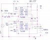
I've read in a google book that if a high gain is needed the it should be obtained in two stages - first one with a fixed gain of 10 and the second with a max gain of 100. The output of the second stage goes into the comparator witch will lit the led and close the opto-coupler.

Do you think that the circuit will work?
Should i use a max gain of 500 in the first stage and the second one use it as comparator (without the 393 and adding a 2n2222 at the output of second stage)?

Thanks
 

Attachments

  • Mic_V2.JPG
    Mic_V2.JPG
    68.5 KB · Views: 1,002
The LM393 is open collector and will not source any current to drive the LEDs.

D1 will prevent any supply current from getting to 0V. What is it supposed to accomplish?

If R1 and R2 are supposed to be a divider they are not connected correctly.
 
Isn't the idea that the average sound level is supposed to switch the output? What you have built will switch the output on/off on a an audio cycle-by-cycle basis, which is not what I think you want.

You need to amplify the audio, then rectify the audio to get the peak value, filter the rectified audio to create an average level (with the appropriate time constant), and then feed the average level to the comparator.
 
OK
when the mic detects a water drop sound i need the transistor from the optocoupler to be in ON state.
I've attached the new schematic of the circuit. V1 simulates the electret
Please ignore the optocoupler transistor connections
 

Attachments

  • Mic_V2.JPG
    Mic_V2.JPG
    71.7 KB · Views: 677
Last edited:
You haven't addressed any of the issues raised by mneary or me...
 
Your 2.25V is actually 4.5V because C2 still blocks blocks R2 from being the bottom half of the voltage divider.

D1 is faced in the right direction so it doesn't disable the circuit, but I still see no purpose for it. It just wastes 0.65V making your 4.5V actually 3.85V. Maybe it's left over from an earlier project.
 
The LM3933 is open collector and will not supply base current to Q1.

Congratulations the LED is hooked up correctly. I assume you plan to do likewise with the opto.
 
I put D1 in the circuit to remove the risk of the reverse battery connection, but it can be removed.
Regarding C2 i read that is needed as a "power reserve" for the op amplifier...so it can be removed also
"The LM393 is open collector and will not supply base current to Q1" this means that i have to use a pull up resistor on the output? to be honest with you i didn't read the data sheet of this circuit, but i will download it and take a look.

PS: Some mistakes are indeed the result of Copy Paste from other projects, i 'll try to check them from now on
 
Last edited:
The first preamp opamp is inverting with an input impedance of only 1k ohms which "shorts" the fairly high output impedance of the electret mic and the 1k resistor that powers it. This opamp should have an input impedance of at least 10k ohms which is made by increasing the values of the gain-setting resistors or using a non-inverting amplifier.

The input offset voltage of the second opamp and/or the comparator might make the circuit turn on the output all the time. Therefore the comparator's trigger voltage needs to be adjustable.

The comparator will probably oscillate all the time because it does not have any hysteresis which is mentioned in its datasheet.
 
maybe this will sound stupid to you but i have to ask

If i make the gain of the preamp variable then i can adjust the amplitude of signal at the comparator input above or below 2.25v. In this case why do i need to adjust the offset voltage of the comparator?

PS: I just realize the mistakes i made in the first circuit: wrong position of C2 and also a missing capacitor at the input of the first op amp. I'm sorry ...i promis to check the schematic twice before posting:eek:

I think i just got my reply ..the signal will oscilate arround 2.25v
 

Attachments

  • Mic_V2.JPG
    Mic_V2.JPG
    73.2 KB · Views: 240
Last edited:
You still haven't put a pullup resistor on the output pin of the comparator and you need a current limiting resistor to the base of the NPN switch.
 
can i put a 500 gain in the first half of the lmv722 and use the second one as comparator? because i'm not interested in sound quality ...just sound waves amplitude (detect water drops splash from 30-40cm)
 

Attachments

  • Mic_V2.JPG
    Mic_V2.JPG
    77.9 KB · Views: 222
You still haven't put a pullup resistor on the output pin of the comparator and you need a current limiting resistor to the base of the NPN switch.
You do not need a current-limiting resistor into the base of the transistor. The pullup resistor sets the amount of base current.

If you do not adjust the DC trip voltage of the comparator then its input offset voltage and/or the input offset voltage of the second opamp might make it turned on all the time without a signal.

If you do not add hysteresis to the comparator then it will probably oscillate all the time.

The duration of the output will be extremely short and might not trigger the camera's shutter.
 
the out put of this circuit will be the input for a delay one
actually the led and the opto coupler will be at the output of the delay circuit
I try to make the design by pieces. I will need to redesign also the photodiode trigger (bwp34) because now i want to trigger to flash from other camera, lightning and led (white led and IR led)
see below the delay circuit

the delay is made for the light sensor (is needed here a lot) but if i set it to minimum i will get a 10ms delay from the first stage.
In the circuit that i use bc547 as preamp and 1/2lmv722 as comparator the circuit trigger just fine , the problem there was the gain of the preamp, that's way i switch to op amp
 

Attachments

  • 556.JPG
    556.JPG
    77 KB · Views: 358
Last edited:
here is the complete circuit
i removed the lm393 and used 1/2 lmv722 as preamp and 1/2 as comparator
 

Attachments

  • CompleteSoundTrigger.JPG
    CompleteSoundTrigger.JPG
    92.1 KB · Views: 193
Two things: Now you need a base resistor and there is no DC path to ground for the bias current on the inverting input of the second opamp.
 
Last edited:
Two things: Now you need a base resistor and there is no DC path to ground for the bias current on the inverting input of the second opamp.
If the inverting input connects through a resistor to ground then the output of the opamp will always be high.

Simply remove C4 and let the +2.5V output of the first opamp bias the inverting input of the second opamp at +2.5V.
 
Interesting problem. I found some explanations here **broken link removed**

what i can't understand now is why the first op amp shouldn't have the same resistor? and why use a 100k to 1M resistor when from the equations Rbias=R1||R2 (R1,R2 are the resistors that sets the gain)?
 

Attachments

  • CompleteSoundTrigger.JPG
    CompleteSoundTrigger.JPG
    95 KB · Views: 218
Your opamp is inverting with a low input impedance of 2.2k ohms. Its gain is as calculated if it is driven from a very low impedance but the electret mic is a fairly high impedance. The electret mic is shorted by the low input impedance of your inverting opamp and the gain of the opamp is much less than what you want.

Again I say, use a non-inverting opamp amplifier that has a high input impedance.
 
Status
Not open for further replies.

Latest threads

New Articles From Microcontroller Tips

Back
Top