eric,
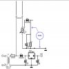
I think it would be better to put multiple C3s and R1s all on the input of the analog switch with P1s and the sensors. Otherwise C3/R1 have to equilibrate with each new selection. Not having built this, I don't know if the time would or would not be significant.
Ken
I think it would be better to put multiple C3s and R1s all on the input of the analog switch with P1s and the sensors. Otherwise C3/R1 have to equilibrate with each new selection. Not having built this, I don't know if the time would or would not be significant.
Ken