Continue to Site

Welcome to our site!

Electro Tech is an online community (with over 170,000 members) who enjoy talking about and building electronic circuits, projects and gadgets. To participate you need to register. Registration is free. Click here to register now.

  • Welcome to our site! Electro Tech is an online community (with over 170,000 members) who enjoy talking about and building electronic circuits, projects and gadgets. To participate you need to register. Registration is free. Click here to register now.

hi & need help

Status
Not open for further replies.

haggis@home

New Member
evening all ...

just wanted to say hi and ask for some help , i used to play with electronics a very long time ago . i now find my self wanting to get back into electronics and struggling ..

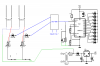
i wanted to make some thing useful for my comeback . i want to make a plant moisture meter for my 4 plants , i have found a circuit that fits the bill but i want to make it a 4 channel unit but am lost . the one i have found is this one (hope i am allowed to post a link , if not mods please feel free to delete)

Soil Moisture Tester

i like the amount of leds this one has , but want to change it slightly . i have a pc PSU to use to power it so the transformer on it would be not needed , and i would love to be able to get the circuit to do four plants at once and constantly monitor there wellbeing ..

do you think it is possible ? and can any of you help ?

thanks and hope to be able to give what little knowledge i have back

Scott
 
The circuit needs the transformer. Besides providing DC to power the circuit, it also provides AC for the probes. Running AC through the probes prevents them from polarizing and corroding over time. You will not have that on the PC power supply.

Do you want to monitor and display the moisture from all 4 pots at the same time, or do you want to have one display and manually switch the display to each pot?

Ken
 
You will have to make 4 of the above circuit to monitor each one of them separately...
and yep...KMoffett is correct u cant get AC power from an pc power supply
 
It would be possible to rapidly multiplex inputs from four sensor/P1/D2/C3/R1 units into one LM3914, and synchronously multiplex its output to 4 sets of LED. The four columns would appear to be indicating all four pots at once. But, unless that's what you really, really need, I would use four sensor/P1/D2/C3/R1 units and a SP4T switch.

Ken
 
This is the schematic for a 1 wire network soil moisture tester. It may not be of interest to the OP because a computer is required to communicate with one wire devices. I have included it here on the chance that others searching for soil moisture testers may find it useful.
 
thank you all for your interest , comments & questions , please keep them coming :D


KMoffett ...

yes i would like to monitor the four pots at the same time on four separate banks of leds , say about 3-6 leds per bank . do you have some ideas ?


ntoniodilen ...

yes i know about the psu not giving AC , i was hoping to perhaps integrate it into the design (secure it under the bench the plants sit on ) by ditching the transformer and trying to keep the cost down a little . but tbh honest i can see why now the person who designed it opted for AC , the less corrosion of the rods the better .

again thanks all


3v0 ...

thank you most kindly for looking about for me :D , i have been googling and that board and lots of others keep popping up . i have saved it in my favourites , not for me at the mo though . there is a hell of a range of uses for it all :eek: . i don't think i am ready for that yet , i am really set on trying to get this project working and should be a good learning curve
 
KMoffett ...

yes i would like to monitor the four pots at the same time on four separate banks of leds , say about 3-6 leds per bank . do you have some ideas ?

It would be four iterations of the "sensor/P1/D2/C3/R1". The output of each would be tied to an analog input of an analog switch such as a CD4066. The analog outputs of all of the analog switches would be tied together and to the LM3914's input. Each of the 4 strings of LEDs would be tied, on the high side to a PNP transistor. Each of the the 4 digital inputs of the 4066 would be connected to one of 4 outputs of a 1-of-X counter such as a 4017 or 4022. The counter would be configured for recirculating 4 outputs:0,1, 2, and 3. The 4 counter outputs would, through 4 inverters (logic or transistor), also be connected to the bases of the PNP LED string drivers. A clock such as an LM555 astable would continually increment the counter. When counter output 0 is high the sensor unit "1" is connected to the 3914's input and the first string of LEDs is powered, indicating the soil resistance of pot "1". When counter output 1 is high the sensor unit "2" is connected to the 3914's input and the second string of LEDs is powered, indicating the soil resistance of pot "2". And so on for counter outputs 2 and 3. Then it starts back at 0. If clocked fast enough, ~120 Hz, all of the LED strings appear to be on.

ken
 
It seems like four LM3914s would be simpler than one LM3914, a counter, a multiplexer, four inverters, and four PNPs.
 
It seems like four LM3914s would be simpler than one LM3914, a counter, a multiplexer, four inverters, and four PNPs.

Yeah, probably. It was just a possibility. ;)

Ken
 
ehmmm ... yeah . its safe to say there ken you know your shizzle , its also safe to say i don't ...

i wish i had carried on with electronics instead of living in the pub :( .

so what do people think ? is it possible ? or have i bitten off more than i can chew with this idea ?
 
Last edited:
ehmmm ... yeah . its safe to say there ken you know your shizzle , its also safe to say i don't ...

i wish i had carried on with electronics instead of living in the pub :( .

so what do people think ? is it possible ? or have i bitten off more than i can chew with this idea ?

hi,
You could use either a HEF4051 or HEF4052 analog multiplexer ic, to select the input signal to the LM3914.

Have 4 pairs of rods, driven by a 6V low power transformer [ for the ac signal source]

Do you follow OK.?:)
 
If conditions are kept constant for all 4 plants, ie water, sunlight, etc, then a single monitor might suffice. Would simplify things.
 
hi Scott,
Look at this rough dwg, only 2 sections shown, but it can do 8 pots!!!
 

Attachments

  • Image1.png
    Image1.png
    161.1 KB · Views: 167
Last edited:
The resistance of the HEF4051 seems high, will that suffice?
 
OMFG ... Eric ... your a utter darling :D:D:D that looks sweet thank you very much , and it can do eight pots :eek::D . if i may ask , is HEF4051 a IC ? one other question , looking at the parts list for the original . the resistors what sort of wattage ones should i get ?

and i also see you have the dragon as your avatar , you from wales ?
 
Okay, keep your sloppy kisses personal...:) The part is available here.
Digi-Key Part Search+

Eric is a good man is he not :)

Utter Darling, and you are sweet... You must be a chick...:D
 
lol no i am a straight bloke with three kids , i picked up the word when i was in Cardiff for 20 years ... old habits die hard . and yes Eric seems to be the the dude :D

i have just checked with farnell and they seem to have stock :D
 
Status
Not open for further replies.

Latest threads

New Articles From Microcontroller Tips

Back
Top