Continue to Site

Welcome to our site!

Electro Tech is an online community (with over 170,000 members) who enjoy talking about and building electronic circuits, projects and gadgets. To participate you need to register. Registration is free. Click here to register now.

  • Welcome to our site! Electro Tech is an online community (with over 170,000 members) who enjoy talking about and building electronic circuits, projects and gadgets. To participate you need to register. Registration is free. Click here to register now.

Help with Scoreboard...

Status
Not open for further replies.

Oxbo Rene

New Member
Good morning;
For the last year > I have been struggling to build a scoreboard for my son.
My son is a coach at a high school and he asked me if I could build him a scoreboard for his wrestling team.
I decided I'd try it, but fast got bogged down and went to the "other" forum first (All about Circuits), looking for help.
And, I did find help, mostly if not almost entirely from one person there. He's an amazingly informed individual and has practically hand fed me for more than a year now.
However, I know that I have become an absolute pest over there, especially to him. Now I suspect he has finally washed his hands of me, and, I guess I can't blame him.
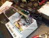
I'm almost done with this scoreboard, just got to figure out what's wrong with the conversion from the console (small unit containing everything that works pretty much perfectly) through the 10ft cable to the big board.
I found Mr Gibbs's aid (thread) to the fellow concerning the exact same kit that I was using (Velleman-K8035)."Multiplexed signals to drive large 7 segment LEDs"
And this person on the other forum helped me with the buffering to transit the 10ft cable.
I have just today gotten it all fabricated and wired up, turned it on and, is sorely not working properly, have troubleshot it to death and just can't see any reason it doesn't work properly, but, it doesn't.
I'm so embarrassed to have aggravated this individual for so long over there with my constant problems, and having him finally cross me off, I'm just at a loss to know what to do after investing so much time and money in this thing.
Am taking a chance reaching out to you guys for my final need, getting the big board LEDs acting correctly, I certainly don't desire to aggravate anyone else to death.
This thing is just so close to being finished, and I'm so lost....
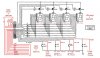
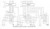
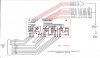
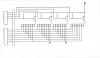
If you happen to have the inclination to take a look at my drawings I'd certainly appreciate it, and would fully understand if you chose not to mess with it.
Thanks for your time,
Oxbo Rene
 

Attachments

  • Kit Diagram ..jpg
    Kit Diagram ..jpg
    111.1 KB · Views: 852
  • Buffer Board..jpg
    Buffer Board..jpg
    62.2 KB · Views: 345
  • Buffer board PCB &#6.jpg
    Buffer board PCB &#6.jpg
    90.8 KB · Views: 319
  • MPSA64 LEDs Circui&.png
    MPSA64 LEDs Circui&.png
    134.2 KB · Views: 300
And here are a couple more Pics...
The drive transistors for T1-T4 are MPSA64 Darlington's.
The real time values were done breadboarding one LED segment and DP, etc.
And the problem is, the LEDS almost light, but are dim, and don't even try to follow the console clock LEDs.
P3270620..JPGMPSA64 LED Biasing&.pngP3040608..JPGP3270621..JPG
 
Last edited:
And here are a couple more Pics...
The drive transistors for T1-T4 are MPSA64 Darlington's.
The real time values were done breadboarding one LED segment and DP, etc.
And the problem is, the LEDS almost light, but are dim, and don't even try to follow the console clock LEDs.

hi,
Can you post a link to that other Velleman thread, I have searched but cannot find it.
 
First off = What is not working properly? Looks like just three segments ?
Seeing how they are all the same segment, are the 2804 outputs to these segments working?
Do the segments work?
Perhaps a missed solder joint?Not looking closly at the PCB perhaps a jumper missed? or perhaps the board is missing a jumper hole or ?
Verify that you have voltage at the three segments not working then start at that point (no voltage) work towards the source until you locate voltage. Could be (IMO) just a bad or missed solder joint or jumper? IF THATS ALL THATS WRONG? of the

Yep got voltages everywhere they're supposed to be.
I had at one point exchanged the one LED where the "a" segment was lit up with another, and it lit up in the other spot, suggesting that the other LEDs were burnt out, pulled all LEDs out and checked them, they all check out OK.
Then checked all the sockets, cleaned all the LED pins......
How about this -> I disconnect T1 (Thousands digit) power (the one with the "a" segment lit) and ALL the other "a" segments light up !!!!!
Actually the one "a" segment is running at 31ma, a little high, but I figure that's because the others are not pulling current.
The other segments look bright in the photo (in the dark), but are only running at 4ma, they're almost indistinguishable in the daylight.
And the main thing, I see no replication of the console clock LED operation at all.
They just almost work, but flat out don't change states to mimic a constantly changing clock operation.
Am certainly praying that I can find a missing jumper or something simple, I need this thing to be out iof my life, it has consumed me for sooooo long.
Is not like a 555 project one can just toss aside, etc....
 
hi oxbo,
Whats the specification of your power supply.?
Going thru the dwgs now.


EDIT:
I believe the Velleman kit output drive signals are TTL levels.???

On the buffer pcb you show 74C14 inverters using a 12V supply...??

Can you confirm this point.??

EDIT2:
Which end of the 10 ft cable is the buffer pcb.?
 
Last edited:
hi oxbo,
Is there a problem getting the answers to my questions..?
 
hi oxbo,
Whats the specification of your power supply.?
Going thru the dwgs now.


EDIT:
I believe the Velleman kit output drive signals are TTL levels.???

On the buffer pcb you show 74C14 inverters using a 12V supply...??

Can you confirm this point.??

EDIT2:
Which end of the 10 ft cable is the buffer pcb.?


Correction--> In above post I state something to the effect that "Removing power to T1, the "a" segment goes out but all the other "a" segments light up = wrong......
Just removing the T1-"a" segment connection, results in this particular segment going out, but indeed the other "a" segments do come on, however, everything is at reduced power (other than the Dp's which I connected to gnd via their respective resistors).
Checking, I definitely have 11.2V on the collectors of all the T1/T2/T3/T4 transistors.
Mr Gibbs;
Power supply is a 12V/ 3.5A Regulated Switching Pwr Supply, bought online.
The MM74C14 is Schmitt Trigger inverters, yes they operate at 12V.
But, I would ask why would the chips' powering status have anything to do with the inputs/outputs to the inverter gates ? Also have all unused inputs grounded.
Buffer board is located two boards below the kit board in the console.
Attached is pic of inside of console, the Kit board, then the 2-teams scores board, and the next board would be the "Buffer" board, but I had not installed it when the pic was taken, etc
 

Attachments

  • P6200297..JPG
    P6200297..JPG
    186.4 KB · Views: 247
Last edited:
hi oxbo,
Is there a problem getting the answers to my questions..?

Sorry, running in/out trying to troubleshoot/investigate/looking up stuff, etc.
I'm thinking that perhaps just to eliminate the possibility of a bad chip on the buffer board, I should go in and substitute to see what happens......
 
The MM74C14 is Schmitt Trigger inverters, yes they operate at 12V.
But, I would ask why would the chips' powering status have anything to do with the inputs/outputs to the inverter gates ? Also have all unused inputs grounded.

hi,
Look at this image, you can see the 74C14 input levels for a Vcc of +10V, for +12V they are even higher/

Power the 74C14 with +5V, not 12V,

The ULN 's are CMOS compatible so the 74C14 will drive OK.

Do you follow OK.?

AAesp08..gif

EDIT:
The buffer pcb should be at the Velleman end of the 10ft cable.


EDIT2:
As you are using 5V logic from the Velleman, the ULN2004 should have been ULN2003 and the ULN2804 should be ULN2803.
You cannot level shift the 5V logic levels to say 12V using the 74C14.

I will keep going thru your drawings, but I can already see why you are having problems.
 
Last edited:
hi,
Look at this image, you can see the 74C14 input levels for a Vcc of +10V, for +12V they are even higher/

Power the 74C14 with +5V, not 12V,

The ULN 's are CMOS compatible so the 74C14 will drive OK.

Do you follow OK.?

View attachment 40837

EDIT:
The buffer pcb should be at the Velleman end of the 10ft cable.


EDIT2:
As you are using 5V logic from the Velleman, the ULN2004 should have been ULN2003 and the ULN2804 should be ULN2803.
You cannot level shift the 5V logic levels to say 12V using the 74C14.

I will keep going thru your drawings, but I can already see why you are having problems.

Ah !
So, hopefully, I drive the Inverter chips with 5V and everything will work ???
I see your edit #2 and think "I have to switch the ULN 2/8 o4's with 03's ?
But see your earlier statement where you say "The ULN 's are CMOS compatible so the 74C14 will drive OK).

So my question is -->
Do I have to switch out the ULN28004 and ULN2004A' with ULN28003 and ULN2003A?

Thank you so much, this is "NEW" info that was totally overlooked on the other forum, and hopefully will end my headache.
Yes, the buffer board is approx 1.5 inches away from the kit board (I did that based on reading your guidance to the young fellow, way back).

I will now get busy hooking up a 5V voltage regulator to pwr the board, etc....

You're a Godsend Mr Gibbs, thanks so much, I pray I can salvage this thing.
Still have to fab up the Guest/Home team scores stuff, but that'll be a breeze..
 
hi,
I think we can exchange the 74C14 for a 74LS07 and so keep the ULN's as they are now.

You will have to add a pullup resistor to +12V to each of the 74LS07 outputs and supply the 74LS07 with +5V, thats no big deal.

If you look at that link you PM'd me, you can see that we used the 74LS06 which is a non inverting version of the 74LS07.

I will post a drawing tomorrow showing how to rewire that section.

Us old guys have to help out you young Uns.!:rolleyes:
 
hi,
Look at this image.

View attachment 40842

OK, got that ! ! !
Heading to the laboratory......(back porch).........
Might have to order the 74LS06'S.
Will get back when I get this fab'd......
Tx's so much.....

P.S.-> The kit uses a UA7805 5V regulator, that reg is capable of providing 1.5A, I think I'd be safe if I tapped into it for the 5V needed to drive the 74LS06's, can you concur ???
Or should I fab up another 5V reg just for driving the chips?????
 
Last edited:
Now im confussed?
The 7414 is an inverter while the 7407 is no so the uln 2004 will work backwards so to speak.
The uln2004 is designed to sink not source. If one segment works then why not the others?
I see mention of two power supplies one being a 7805. Is it possable that the ground between them is not secure?
Just curious??
 
OK, got that ! ! !
Heading to the laboratory......(back porch).........
Might have to order the 74LS06'S.
Will get back when I get this fab'd......
Tx's so much.....

P.S.-> The kit uses a UA7805 5V regulator, that reg is capable of providing 1.5A, I think I'd be safe if I tapped into it for the 5V needed to drive the 74LS06's, can you concur ???
Or should I fab up another 5V reg just for driving the chips?????

hi,
For the two 74LS06 the existing 5V should be OK.
BTW: I assume you have a Velleman 0V line connection to the 12V buffer pcb 0V.
 
Now im confussed?
The 7414 is an inverter while the 7407 is no so the uln 2004 will work backwards so to speak.
The uln2004 is designed to sink not source. If one segment works then why not the others?
I see mention of two power supplies one being a 7805. Is it possable that the ground between them is not secure?
Just curious??

hi D,
The output from the Velleman pins are active low [0v], so the low on the 74LS06 input will set the output high, this high when connected to the ULN's input will set the ULN's output low.
So the LED Anode driver will be enabled, connecting the anode to +12V.
Also the for the Segments, when the segment is pulled low it will light, providing the LED's anode is enabled.

The basic problem with the existing 74C14 is that its powered from 12V, so the input required to enable to turn on is approx 7V, which the Velleman cannot deliver as its a 5V system.

I suspect someone had the the idea of using the 74C14 as a level shifter 5V to 12V, but it will not work correctly.

The 74LS06 even though its TTL level inputs has a high voltage o/c output which is going to be connected to +12V, so its a level shifter.

Are you now unconfused.?:)
 
Last edited:
Status
Not open for further replies.

Latest threads

New Articles From Microcontroller Tips

Back
Top