djvsmarkviii
New Member
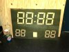
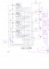
I have a up/down counter kit I built that utilizes a microcontroller to drive 4small 7segmenet leds to display the time count. I want to use the multiplexed signal for the small 7 segment leds to drive much larger 10" led displays that I will be constucting for a large sports scoreboard for my sons Lacrosse team. Each segment will have 8 leds which will end up being 56 leds per digit, * 4 digits= 224 leds for display. I have a manual remote control that will house the counting circuit and all the various switches for the scoreboard. Cable length from remote to display panel will be about 10'. My question is how can I use the multiplexed signal to drive the large display and can I send the multiplexed signal that far? Any help would be appreciated.
")